Rychlá odpověď: A sending card receives and maps the image for an LED wall, then sends the assigned pixel data through its output ports. A receiving card in each cabinet converts that data into the signals required by its LED modules. Use the signal path below to locate mapping, cable, power and module configuration faults.
A sending card and a receiving card occupy different points in an LED display system. The sender accepts a video feed, organizes it for the screen and transmits mapped data over output ports. A receiver inside a cabinet takes the data assigned to its area and produces the module level signals that illuminate the LEDs. If the screen is blank, scrambled or showing the wrong image area, knowing which stage owns the symptom can save hours of random configuration changes.
This guide follows one frame from source to pixel, then separates the video, configuration and power paths. It describes the common synchronous LED architecture used by many controllers; port counts, loading limits, interfaces and processing features vary by model and should always be checked against the actual hardware manual.
The complete signal map
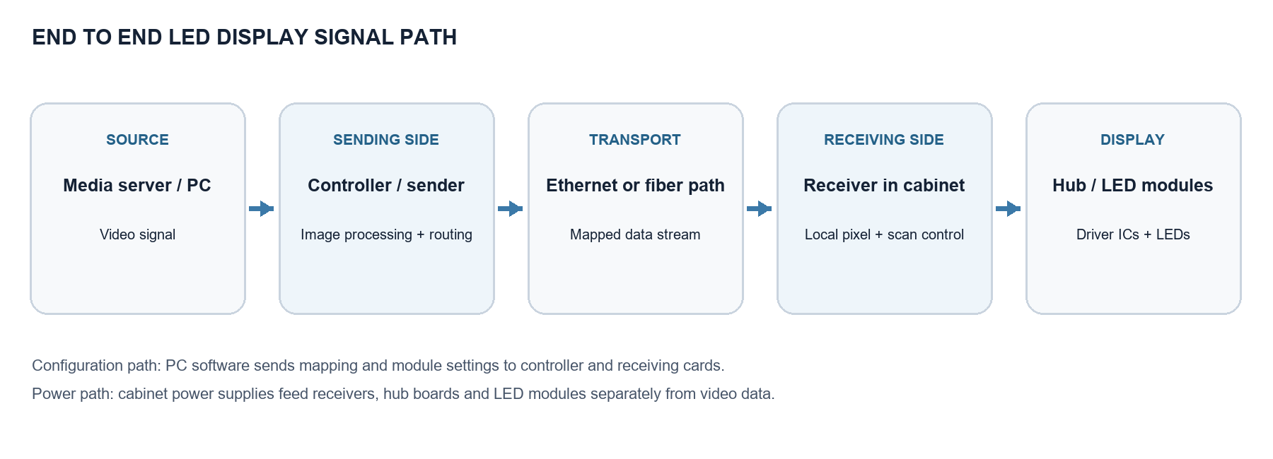
Figure 1 The video path and two supporting paths in a typical synchronous LED display.
The source produces image frames. A controller or sending card accepts an input such as HDMI, DVI or SDI, depending on the model. It may scale, crop, synchronize or otherwise process the image, then assign screen regions to physical output ports. An output cable carries the encoded display data to the first receiving card on that port; additional receivers may be connected in the configured order. The receiving card reconstructs the pixel area intended for its cabinet and drives the hub board and LED modules according to the stored module configuration. NovaStar describes sending devices as transmitting input signals via Gigabit Ethernet ports and receiving cards as driving the display.
Three paths should be kept distinct. The video path carries continuously changing image data. The configuration path writes parameters such as cabinet size, port order, module wiring and scan behavior. The power path supplies the controller, receivers and LED modules. A working network link proves neither that the source is valid nor that cabinet power and module mapping are correct.
This distinction also prevents a common mistake during troubleshooting. A laptop can communicate with the controller’s configuration interface while the live video input is absent. Conversely, a controller can detect a video source while the receiving cards have the wrong cabinet coordinates. Treat status lights, software detection and a visible test pattern as separate pieces of evidence. Each confirms only the part of the chain it actually exercises.
What the sending card does
The sending side is the system level distributor. Its first task is to acquire the source at a supported resolution and frame rate. Some installations use a separate video processor before a sending card; others combine processing and sending in one controller. The name “sending card” is therefore a role, not a guarantee that the device is a PCIe card or that it performs every image adjustment.
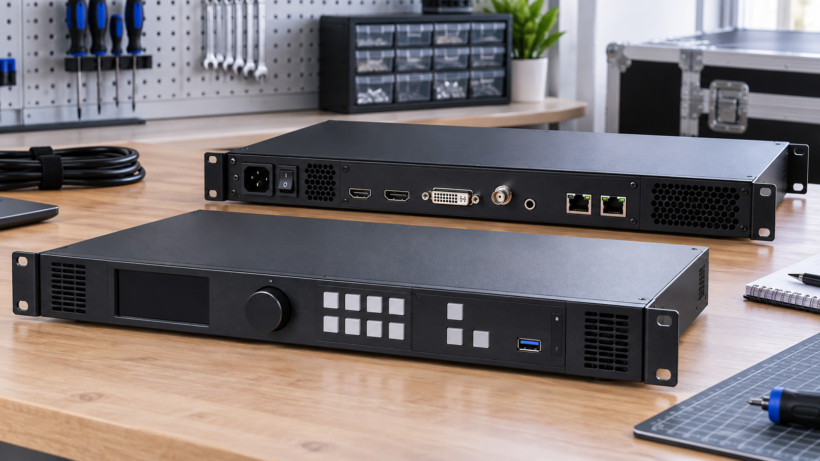
Figure 2 A controller with video inputs and display data outputs. Illustrative image.
Next, the sender maps the logical canvas to its output ports. Think of a 1,920 × 1,080 image as a coordinate plane. A port is assigned one or more regions, and each receiver needs a starting coordinate and a cabinet width and height. The controller packages the appropriate data for its connected receivers. Its total pixel capacity and per port capacity are hardware specific. For example, NovaStar lists two Gigabit Ethernet outputs and a maximum of 650,000 pixels per port for the MCTRL300; that number is an example, not a universal Ethernet limit.
The sender also distributes timing information needed for coherent display. Depending on the platform, it may support input monitoring, redundant outputs, synchronization features or color processing. A backup cable may improve resilience only when redundancy is supported and configured. The Ethernet shaped RJ45 connector is a physical interface here; the link should not automatically be treated as a normal office LAN carrying standard IP video. Follow the vendor’s wiring and switching guidance.
Input resolution and physical screen resolution are related but need not be identical. A processor may scale the source before the sender distributes it, and a sender may crop or remap part of its input canvas. Document those transformations explicitly. Otherwise an image that is correctly delivered to every cabinet can still appear stretched, clipped or offset. Where several controllers form one wall, verify their shared timing and stitched coordinate plan with the equipment’s supported synchronization method.
What the receiving card does
A receiving card is the cabinet level translator. It identifies the image area assigned to its cabinet, interprets incoming display data and emits parallel color data plus timing and control signals to the modules. Those signals interact with the hub board, driver ICs and scan architecture. Receiver specifications commonly identify the number of RGB data groups, supported scan modes, output connector type and maximum pixel load. NovaStar’s MRV line, for example, lists model dependent HUB75E outputs, parallel RGB groups and scan support.
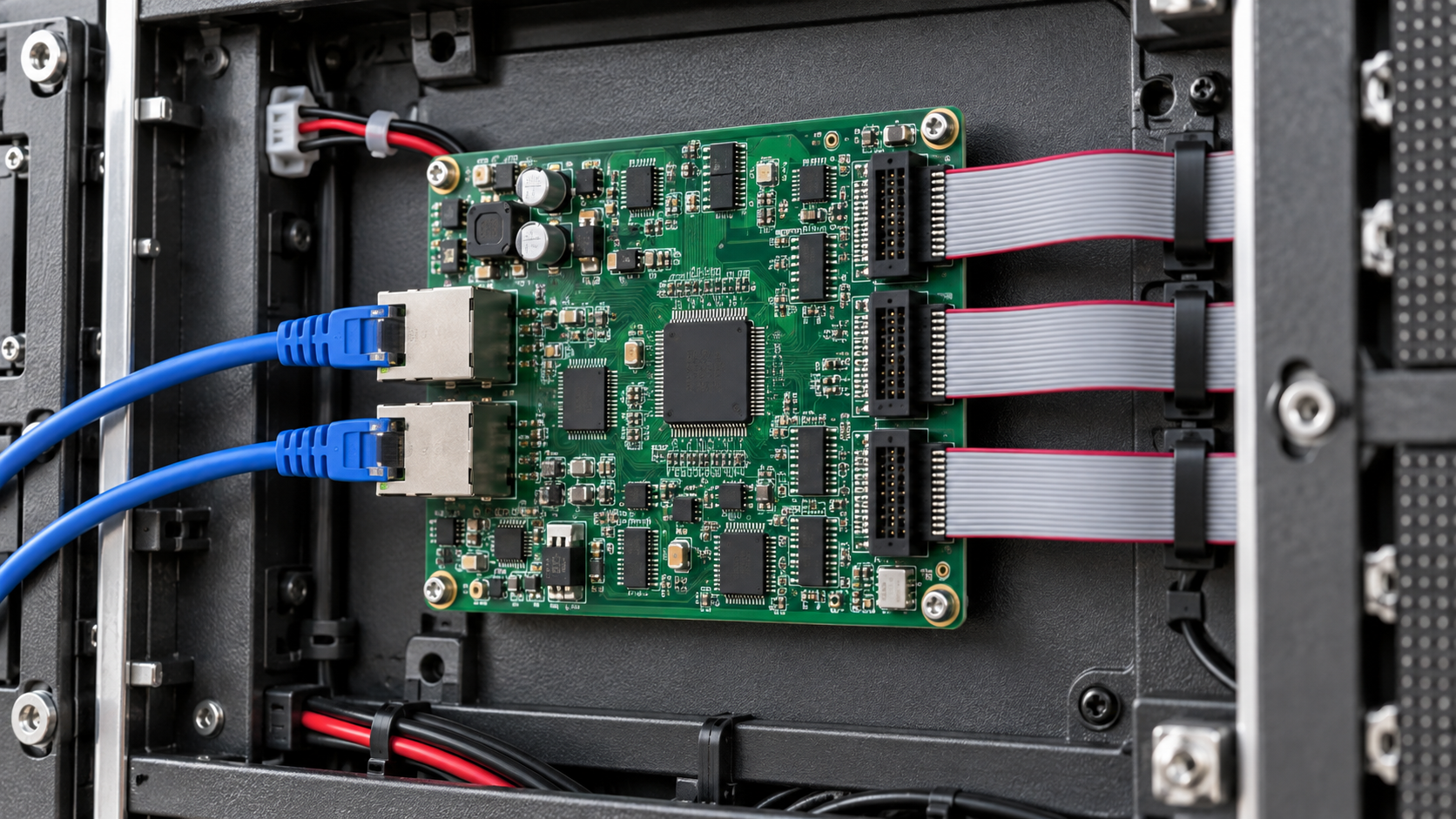
Figure 3 A receiving card mounted inside an LED cabinet. Illustrative image.
The receiver is where module details become critical. A module may use a particular driver IC, scan ratio, data group arrangement, decoder and polarity. Settings that do not match the physical module can create repeated or shifted sections, missing colors, ghosting or a dark display even while the upstream image is valid. Colorlight’s LEDSetting manual explicitly includes receiver data groups, driver IC, module size, route direction, data polarity and OE polarity in its configuration workflow.
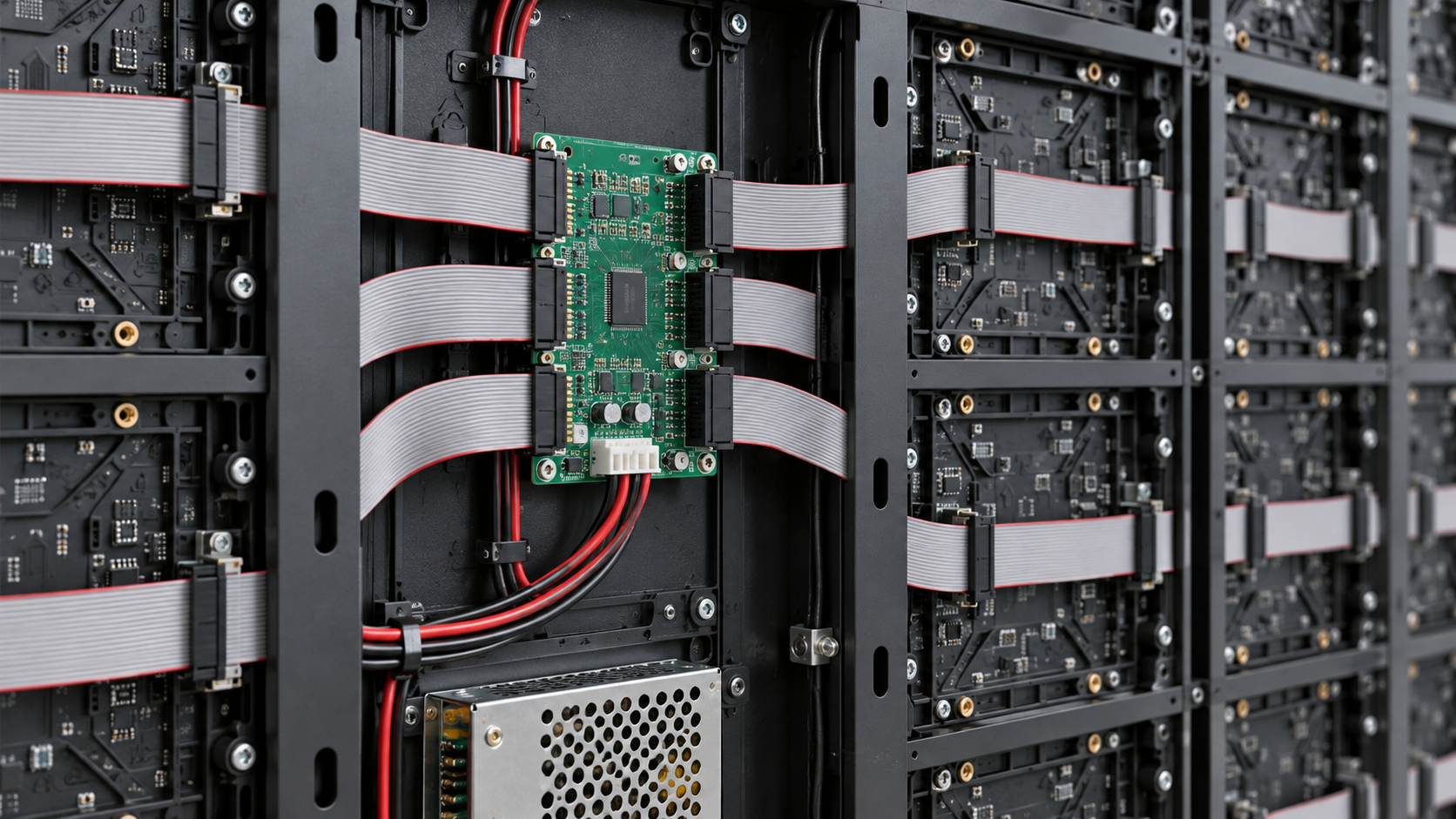
Figure 4 Ribbon cables and a hub board behind LED modules. Illustrative image.
Many receivers also store calibration data or support brightness and chromaticity correction, monitoring and backup features, depending on model. Such features do not change the basic division of labor: the sender decides where data goes across the screen; the receiver turns its allocated data into electrical behavior suitable for the local modules.
Sending card vs receiving card at a glance
| Porovnání | Sending card / controller | Přijímací karta |
|---|---|---|
| Fyzická poloha | Control room, processor or controller chassis | Inside an LED cabinet |
| Primární vstup | Video source or processed image | Mapped display data from a sending output |
| Primární výstup | Display data to one or more cabinet chains | RGB data, timing and module control signals |
| Main setup | Input format, canvas, output ports and screen mapping | Cabinet coordinates, module wiring and scan settings |
| Typical failure scope | Entire screen or one output chain | One cabinet or part of a cabinet |
How cabinet mapping turns pixels into a physical screen
A signal map links four coordinate systems: the source image, the sender’s output ports, the receiver’s cabinet area and the module’s internal pixel order. The installer must know both the logical position of each cabinet and the physical cable path. A receiver that is physically second in a chain may need an image region to the right, below or elsewhere, depending on how the wall is assembled.
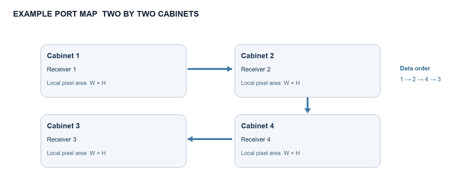
Figure 5 A possible cable order for four cabinets; screen coordinates still need to match physical positions.
Consider four cabinets in a two by two wall. If each cabinet is W × H pixels, their logical starting coordinates are (0,0), (W,0), (0,H) and (W,H). The cable may run across the top row, down at the right and back across the bottom row. Software must map that 1 → 2 → 4 → 3 route to the correct coordinates. If all receivers default to (0,0), every cabinet can show the same upper left image crop. NovaLCT documentation describes that outcome when starting coordinates are reset across receiving cards.
Before configuring, record the module resolution, modules per cabinet, cabinet pixel size, cabinet grid, port assignment and cable sequence. Calculate the load per port from the pixels it serves, then compare it with the specific controller and receiver limits at the intended refresh and color settings. Do not infer capacity only from RJ45 port count. On mixed or irregular screens, document rotation and nonrectangular routing explicitly.
The cabinet map is more than a diagram for installers: it is the reference for later maintenance. Label each output, cable, receiving card and cabinet with the same identifiers used in the software project. Save a copy of the map with the configuration file and record any spare receiver’s firmware and approved parameter file. When a card is replaced, this record makes it possible to restore the exact image area and module behavior instead of guessing from a nearby cabinet.
Diagnose by the size and location of the fault
The whole display is black
Start at the broadest shared components: source output, selected controller input, sender status, output enable and power. Show a controller test pattern if available. If the test pattern appears but live video does not, inspect source format and input selection. If nothing appears, inspect output mapping, the first cable and cabinet power before changing module scan parameters.
One entire port chain is missing
Check that port’s assignment, cable seating and the first receiver in its chain. A failed first link can remove every downstream cabinet. Swap a known good cable only when safe to do so and compare link or status indicators according to the vendor manual. If a redundant path exists, verify that it is actually configured and supported.
One cabinet is wrong or dark
Inspect that receiver’s power, address or coordinate, incoming and outgoing links, and stored configuration. If downstream cabinets still work, the transport path may be intact while the local receiver to module path is faulty. A cabinet showing another cabinet’s image usually points to mapping rather than a dead LED module.
Only part of a cabinet is scrambled
Focus on hub cables, module order, data groups, scan ratio, driver IC settings and polarity. A repeated pattern often indicates an incorrect module data route. Before loading a configuration file, verify that it matches the exact module and receiving card combination; a similar pixel pitch does not prove identical electrical wiring.
Běžné otázky
Can a sending card replace a receiving card?
No. The sender distributes screen data; the receiver generates the cabinet’s local module signals. A working sender cannot directly stand in for the receiver in a conventional modular wall. An integrated all in one product may hide the components, but the functions still exist.
Is an LED receiving card the same as a TV receiver?
No. “Receiving” here means receiving the display data stream from an LED controller and converting it for LED modules. It does not mean receiving broadcast television or decoding a consumer streaming service.
Are sending and receiving cards interchangeable across brands?
Assume compatibility only when the vendor explicitly documents the controller, receiver, firmware and software combination. Similar connectors do not establish protocol compatibility. The same caution applies to cabinet configuration files and backup images.
Does a higher refresh rate come only from the sender?
No. The achievable result depends on the source frame rate, controller settings, receiver capability, scan scheme and driver IC behavior. A 60 Hz video input and a high LED scan refresh are different measures. Check the complete hardware chain before promising a specification.
A practical commissioning sequence
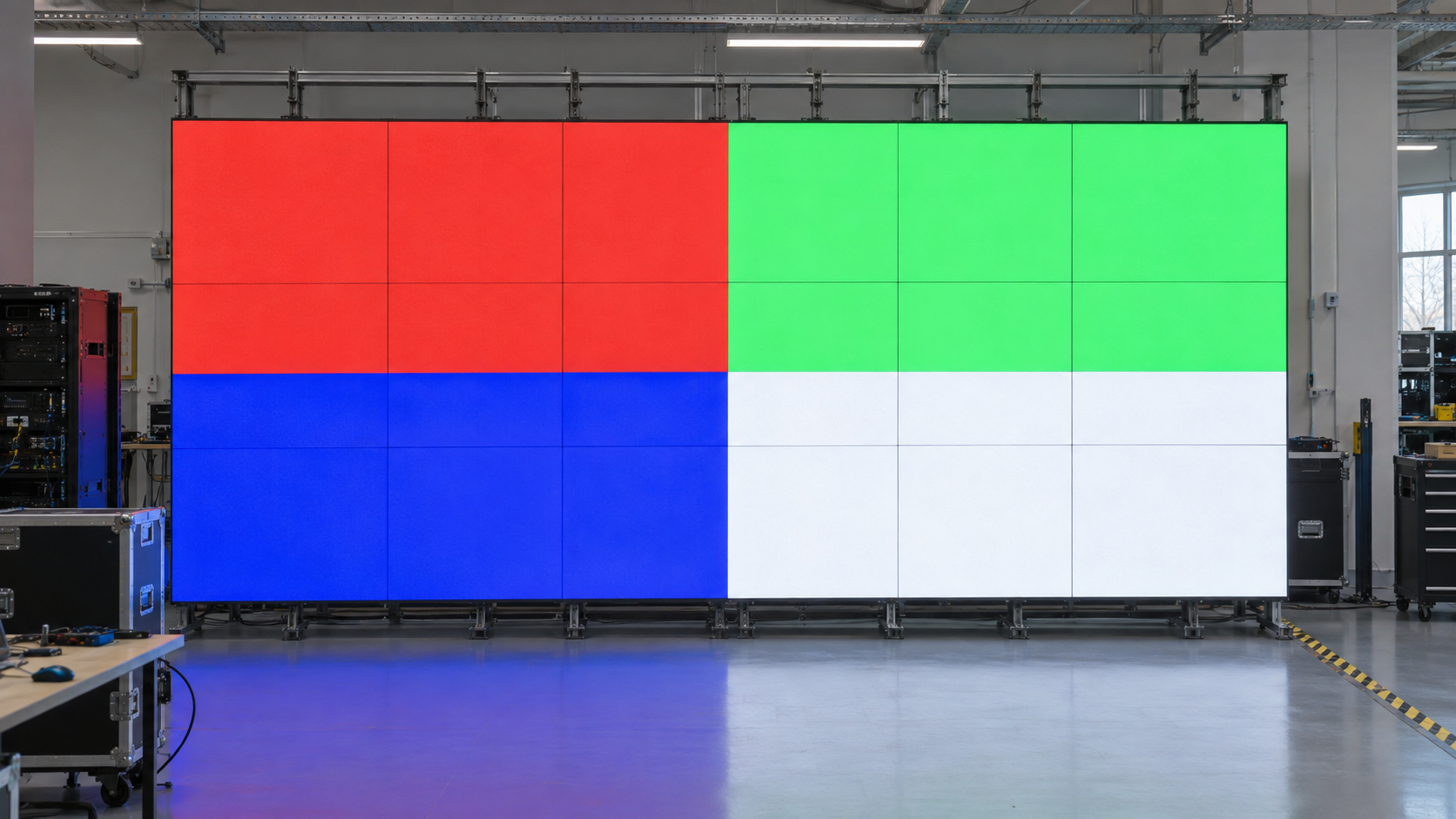
Figure 6 A color test pattern used to check cabinet alignment and color channels. Illustrative image.
- Confirm the source format and selected controller input.
- Set the display canvas and assign each physical output port.
- Connect one known good cabinet, load its exact receiver and module configuration, then check red, green, blue, white and grayscale test patterns.
- Extend the chain in cable order, assigning each cabinet its screen coordinate and checking a mapping pattern.
- Save the verified configuration to the hardware and keep a dated backup.
This sequence localizes errors before they spread across a full wall.
Závěr
A sending card maps the image and delivers each region through the correct output port. A receiving card turns its cabinet’s region into local data and timing for the LED modules. The cable route, screen coordinates and module settings connect those jobs. When the image fails, identify the largest affected area and test each boundary from source to module. This narrows the fault without changing unrelated settings.
For hardware examples, compare LED odesílací karty a LED přijímací karty, then confirm protocol and module compatibility in the manufacturer documentation.