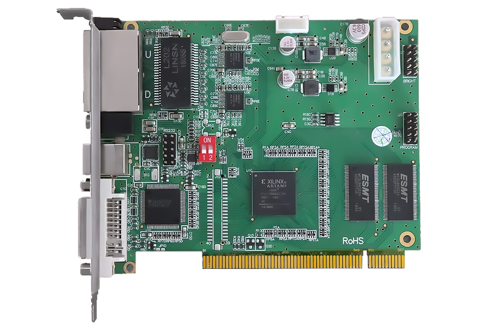
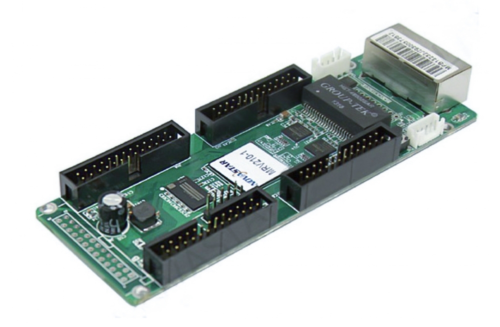
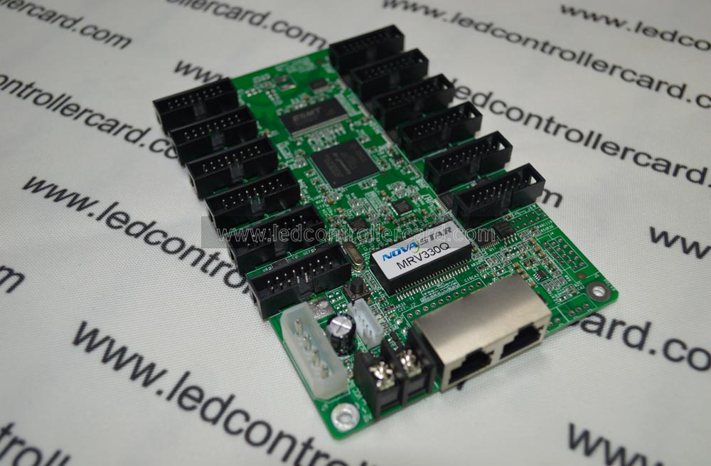
The RV902 is designed for small LED assemblies and background displays where mounting space and module-side connectors matter. Its specification gives separate data-group counts for each output mode.
Matching the data mode
Identify whether the hub uses serial, RGBR′ or parallel RGB signals. The linked RV902 sheet includes the connector definitions used to check those connections before configuration.
技術仕様
| 製品仕様 | |
|---|---|
| Maximum layout | 1024×256ピクセル、デザインによる |
| シリアルデータ | 16グループ |
| RGBR′ mode | 4グループ |
| RGBモード | 5グループ |
| サービス | Pixel brightness calibration and network cable bit-error test |
製品画像と資料


LINSN RV902 LED ディスプレイ パネル受信カードの仕様
よくある質問
1. Can I use all three data-group counts together?
They describe different output modes. Follow the module wiring and pin definitions for the selected mode.
2. What cabinet layout does the sheet list?
It gives up to 1024 × 256 pixels, subject to the LED module design.
3. How can I distinguish a cable fault from a color adjustment issue?
Use the supported network cable error test for the data path. Brightness calibration and color-space conversion address display uniformity.