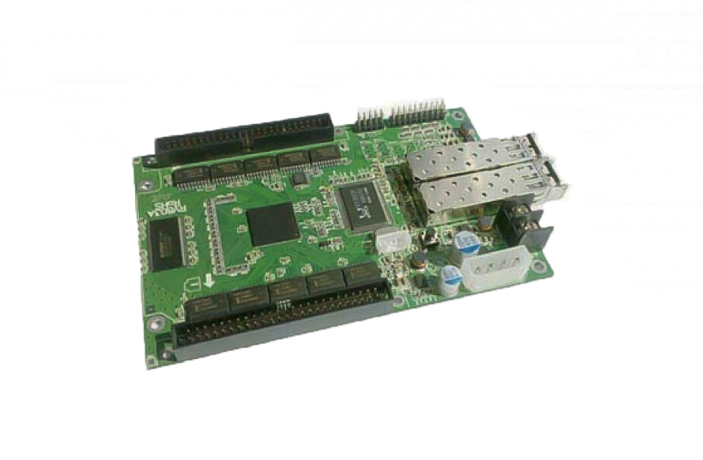
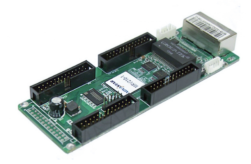
The Colorlight E80 LED receiving card connects an LED display cabinet to a Colorlight control system. It integrates eight HUB75 interfaces for LED modules and supports 16 groups of parallel RGB data or 32 groups of serial RGB data. Use the chip-specific load limits below when planning a cabinet.
Colorlight E80 key specifications
| Item | Specification |
|---|---|
| Module connectors | 8 integrated HUB75 interfaces (J1–J8) |
| Data groups | 16 parallel RGB or 32 serial RGB groups |
| Control area | Normal chips: 64 × 1024 pixels; PWM chips: 128 × 1024 pixels; Shixin chips: 81 × 1024 pixels |
| Scan type | Up to 1/128 scan, subject to the LED module and configuration |
| Network and power | Two interchangeable RJ45 ports; 1 Gb/s; DC 3.8–5.5 V, 0.6 A; rated power 3.0 W |
| Size | 86.8 × 91.7 × 18.4 mm |
Display and maintenance features
- 8-bit video source input, color temperature adjustment, and improved gray detail at low brightness.
- Supports 120/240 Hz high frame rate output in supported configurations; higher frame rates can reduce available load.
- Pixel-by-pixel brightness and chromaticity calibration, cabinet highlighting, on-screen identification, and screen rotation.
- Ethernet cable error monitoring, loop redundancy, and firmware backup for easier fault finding and maintenance.
Planning an E80 installation
Check the LED module’s driver chip, scan type, HUB75 pinout, cabinet resolution, and power supply before selecting receiver card settings. The allowable control area depends on the chip type; the commonly quoted 256 × 256 pixels equals 64 × 1024 pixels and does not describe every E80 configuration. For a specific cabinet design, compare its wiring and load with the linked specification before ordering.
Browse other LED receiving cards or contact us with your module and cabinet details.
Colorlight E80 product pictures


Download the E80 specification
Colorlight E80 receiving card specification (PDF, V4.2.1)
Conclusion
The Colorlight E80 combines eight HUB75 interfaces with chip-dependent loading, calibration, monitoring, and redundancy features. Confirm the cabinet’s driver chip and wiring against the specification to select the right settings.