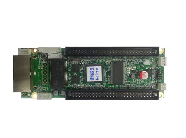
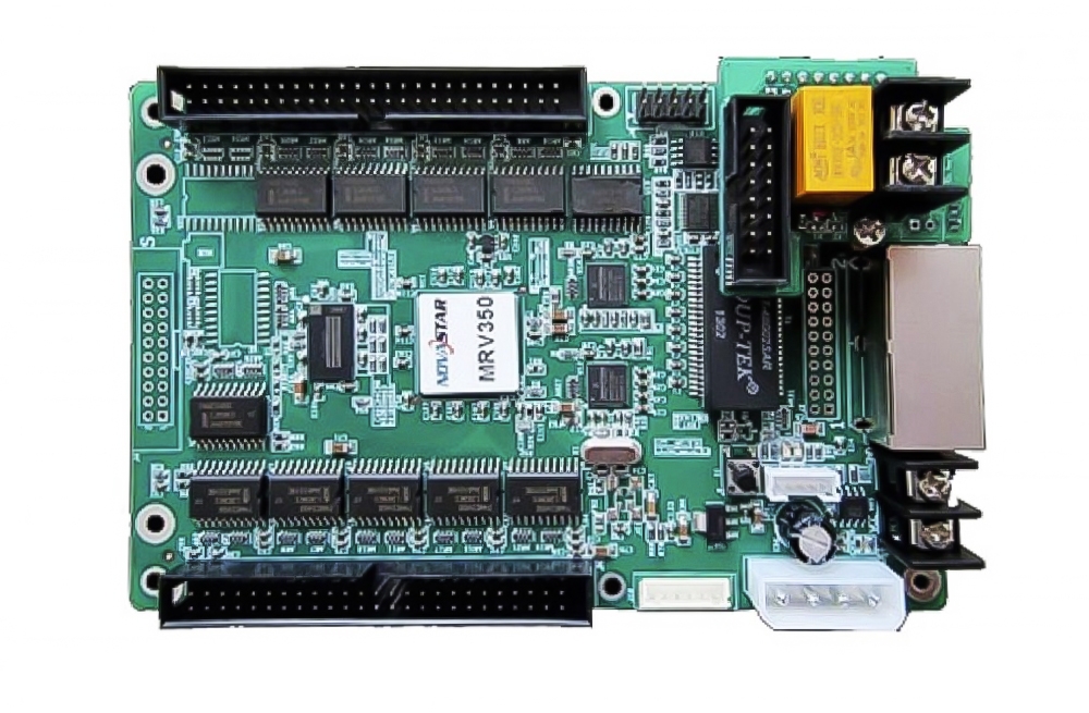
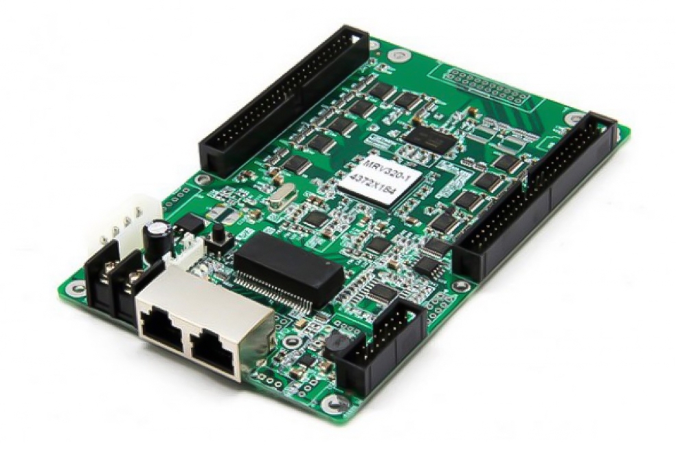
The Mooncell VCSG3-V22D LED receiving card is listed for LED display systems with calibration, monitoring and recovery functions. Its source specifications state a 64K-pixel maximum load and a 3.5–6 V supply range.
VCSG3-V22D specifications
| Parameter | Specification |
|---|---|
| Exact model | Mooncell VCSG3-V22D |
| Maximum card / data-group load | 64K / 8K pixels |
| Supply range | 3.5–6 V |
| Conventional RGB output statement | 16 groups, expandable to 32 |
| Other RGB maximum in source | 21 groups; output-mode relationship not specified |
| Serial output statement | 64 groups, expandable to 128 |
| Driver types | PWM, point-detection and conventional ICs |
| Calibration | Single-pixel calibration; source states no loading-area reduction |
| Network function | Dual cable backup |
| Maintenance features | Saved settings, receiving-card monitoring, environment monitoring and recovery |
Match the board and output mode
Use the full V22D designation when comparing replacement parts. The source page contains different RGB output counts without explaining the operating modes. Confirm the connector layout, driver and expansion hardware before using any of those counts in a cabinet design.
Network backup and intelligent-power arrangements require compatible equipment and configuration. Keep the existing display settings available and verify the screen after replacement.
Frequently Asked Questions
Is this the VCSG3-V22 or VCSG3-V22D model?
The product title and image descriptions identify VCSG3-V22D. Use the complete V22D designation and check the actual board revision when requesting a replacement.
What is the maximum pixel load?
The listed maximum is 64K pixels for the card and 8K pixels per data group. An increased output-group count should not be used to infer a higher card capacity.
Why are different RGB group counts shown?
The source lists 16 conventional groups expandable to 32, a separate maximum of 21, and 64-to-128 serial outputs. It does not define how those modes relate. Verify the intended mode and expansion configuration for the exact board.
Which driver IC types and calibration are listed?
PWM, point-detection and conventional drivers are listed, together with single-pixel calibration without reduced loading area. Confirm compatibility with the actual module driver and configuration.
What needs checking after a card replacement?
Check the model suffix, pinout, supply polarity, saved settings and screen output. The listed recovery and backup functions depend on the complete setup and do not guarantee fault-free display under every condition.
Original receiving-card photos