Biranje između Colorlight 5A-75B vs 5A-75E comes down to how many flat 16-pin HUB75 ribbon headers your cabinet uses and how many parallel RGB data groups your driver ICs demand. Go with the 8-port Colorlight 5A-75B (16 parallel or 32 serial RGB groups, up to 192 x 1024 pixels on PWM chips) for standard 4-to-8-row commercial cabinets. Step up to the 16-port Colorlight 5A-75E (32 parallel RGB groups, up to 512 x 512 pixels) when taller 9-to-16-row cabinets need direct ribbon feeds without stacking a separate hub board.
Spend enough years troubleshooting LED video walls and you’ll pull dozens of Colorlight boards out of rain-soaked signs, touring rental frames, and dusty retail fascias. Most blacked-out or shimmering cabinets trace back to a corroded ribbon latch, a sagging 5 V supply rail, or a tech who tried plugging an 8-port board into a 12-ribbon harness—or renamed a legacy .rcvp file extension on a laptop instead of exporting a valid .rcvbp file from LEDVISION.
Before ordering spares or locking a cabinet bill of materials, let’s walk through what separates the legacy 5A-75, current 5A-75B, dense 5A-75E, and compact i5A-907 on a live shop bench—including HUB75E pinouts, driver IC limits, and clean .rcvbp loading steps.
1. Hardware split: Colorlight 5A-75B vs 5A-75E, 5A-75 & i5A-907
Right out of the anti-static bag, the easiest clue in a Colorlight 5A-75B vs 5A-75E inspection isn’t the FPGA processor—it’s how crowded the black 16-pin headers look along the green PCB. Both cards use hub-less layouts, meaning flat 16-conductor gray ribbon cables jump directly from the receiving card to the modules. Eliminating an extra board-to-board hub backplane removes common vibration faults inside touring frames and mobile trailer walls.
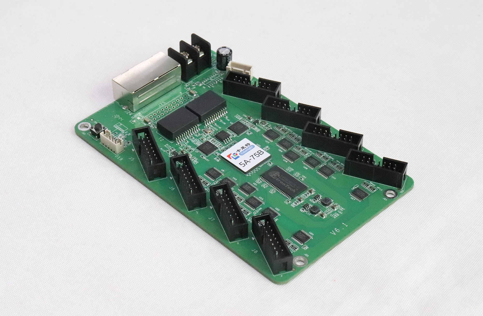
01. 8-port vs 16-port HUB75 connector density
The Colorlight 5A-75B carries eight 16-pin HUB75 headers (JH1 through JH8). Because each HUB75 port sends two vertical RGB channels (R1/G1/B1 and R2/G2/B2), eight headers deliver 16 groups of parallel RGB data (or 32 serial RGB groups). That matches 500 x 500 mm (19.7 x 19.7 in) or 640 x 640 mm (25.2 x 25.2 in) cabinets stacked four to eight module rows high, where each horizontal row receives one short direct ribbon cable.
Step inside a taller 960 x 960 mm (37.8 x 37.8 in) outdoor cabinet or a fine-pitch frame built with twelve 320 x 160 mm (12.6 x 6.3 in) modules, and eight headers quickly run short. You would otherwise have to daisy-chain two modules onto one ribbon—splitting refresh rate in half and raising heat along the driver pins—or mount two separate receiving boards per enclosure. The Colorlight 5A-75E puts 16 onboard HUB75 headers onto one PCB, feeding all 32 parallel RGB data groups from a single Ethernet drop. In a real Colorlight 5A-75B vs 5A-75E cabinet build, avoiding that second receiving board saves two Ethernet patch cords, one 5 V DC power harness, and one extra point of failure inside weather-sealed steel doors.
Also inspect the power screw terminals while the cabinet door is open. Both boards accept 3.3 to 5.5 V DC (target 4.95 to 5.10 V DC under load) through dual parallel power blocks or auxiliary pin-header pads. Using clean 20 AWG copper leads directly from the cabinet Mean Well or Rong Electric power supply keeps logic voltage stable across high-brightness white frames so the FPGA never drops out or resets mid-show.

02. Pixel load ceiling under standard & PWM modes
Never size cards from one generic pixel headline. In any Colorlight 5A-75B vs 5A-75E comparison, real pixel capacity shifts with the driver chip on the module backplane. On the 5A-75B, Colorlight specifies up to 128 x 1024 piksela (131,072 pixels) with standard shift-register chips, 162 x 1024 piksela with Shixin chips, and 192 x 1024 piksela (196,608 pixels) with PWM constant-current chips.
On the 5A-75E, unlocking 32 parallel RGB groups expands manufacturer-rated capacity up to 512 x 512 piksela (262,144 pixels). That 512 x 512 figure represents a hardware upper boundary, not a guarantee that every high-scan fine-pitch cabinet hits 3,840 Hz refresh when filled to the brim. Still, having twice as many ribbon headers lets you keep horizontal chains short.
03. Where legacy 5A-75 and compact i5A-907 fit in
Field techs frequently bump into two siblings on older service calls: the original Colorlight 5A-75 i vitki Colorlight i5A-907. Although the pre-2020 5A-75 also carries 8 HUB75 headers, its older hardware design lacks newer PWM driver definitions added in recent LEDVISION releases. Meanwhile, the i5A-907 isn’t a direct-ribbon card at all—it measures 137 x 48 mm (5.39 x 1.89 in) with five 26-pin headers built to dock onto a die-cast cabinet’s rigid hub board, rated at 256 x 256 pixels conventional load and 1/64 scan.

| Model | Sučelje modula | RGB podatkovne grupe | Nazivni kapacitet opterećenja | Podrška za skeniranje | Primary Cabinet Use |
|---|---|---|---|---|---|
| Colorlight 5A-75B | 8 x 16-pin HUB75 onboard | 16 parallel or 32 serial RGB | 128 x 1024 normal; 162 x 1024 Shixin; 192 x 1024 PWM | Statički do 1/128 skeniranja | 4-to-8-row commercial walls, 500 x 500 mm cabinets |
| Colorlight 5A-75E | 16 x 16-pin HUB75 onboard | 32 parallel RGB groups | Up to 512 x 512 px (scan & chip dependent) | Static through high-scan PWM | 9-to-16-row 960 x 960 mm outdoor & fine-pitch frames |
| Colorlight 5A-75 | 8 x 16-pin HUB75 onboard | 16 parallel RGB groups | Legacy 5A range; varies by board batch | Static to 1/32 typical | Drop-in repairs on older signage builds |
| Colorlight i5A-907 | 5 x 26-pin hub headers (J5 mirrors J1) | 16 RGBR’ or 24 RGB parallel | 256 x 256 px conventional (1,024-col special) | Statički do 1/64 skeniranja | Slim die-cast rental cabinets using a hub backplane |

2. HUB75 vs HUB75E pinouts & scan ratio wiring (1/16 to 1/128 scan)
Buyers often see HUB75 printed beside the sockets on a Colorlight 5A-75B vs 5A-75E board and wonder if it breaks compatibility with modules labeled HUB75E. In practice, both boards share the full 16-pin HUB75E footprint supporting five scan-address lines (A through E). Even so, spending thirty seconds checking silkscreen pins prevents dead rows on custom modules.
01. Address lines A through E: checking pins 8 and 14
Legacy 1/8-scan and 1/16-scan modules only use address bits A, B, C, and D on pins 9, 10, 11, and 12 (leaving pin 8 or pin 14 tied to ground). Higher-density indoor modules running 1/32 scan or 1/64 scan require a fifth address bit (E), typically placed on pin 14—or pin 4 and pin 8 on certain custom layouts.
If an older receiving card forces pin 14 straight to chassis ground, half of a 1/32-scan module mirrors the other half identically. Both the 5A-75B and 5A-75E route address lines A through E across every header cleanly; match the exact module silkscreen labels inside LEDVISION’s pin-mapping screen before saving settings to flash.
02. Flat ribbon cable length limits & crosstalk prevention
More ports on the 5A-75E also shorten cable geometry inside big frames. Try routing eight ribbons from a 5A-75B across a wide 960 x 960 mm (37.8 x 37.8 in) steel frame and outer corner IDC ribbons stretch past 450 mm (17.7 in), swinging directly across noisy AC power lines.
Once unshielded gray ribbon cables exceed roughly 400 mm (15.7 in) at 25 MHz shift clocks, crosstalk triggers green pixel sparkle or dropped data lines in warm weather. Mounting a 16-port 5A-75E centered in the cabinet keeps most ribbons between 150 and 280 mm (5.9 and 11.0 in) for rock-solid high-frequency stability.
03. Upgrading older 5A-75 cabinets to 5A-75B or 5A-75E
Can you drop a newer 5A-75B into a dead cabinet that shipped with a legacy 5A-75? Physically, both feature eight HUB75 headers and 3.3–5.5 V DC power blocks, though hole spacing varies slightly by cabinet bracket. Because the older binary file doesn’t transfer cleanly across hardware generations, pull chip timing and scan geometry from a healthy neighbor card in LEDVISION and compile a clean configuration for the new 5A-75B.
Likewise, you can install a 16-port 5A-75E where an 8-port 5A-75B sat if you plug your eight existing ribbons into ports JH1 through JH8 and leave JH9 through JH16 open—just never the reverse. Walk through our Colorlight 5A-75B wiring checklist before powering unfamiliar cabinets.
3. Driver IC limits: conventional latch ICs vs PWM chips
The biggest trap in evaluating Colorlight 5A-75B vs 5A-75E cards is chasing raw pixel totals while ignoring refresh rate and driver chip timing. Receiving card bandwidth depends heavily on how LED module ICs convert serial video bits into light pulses.
01. How Colorlight firmware drives PWM multipliers
Conventional shift-register drivers (like ICN2037, MBI5024, or SM16207) need constant high-speed clock toggling from the receiving card to sustain grayscale levels, topping out the 5A-75B at 128 x 1024 pixels. Modern PWM drivers (ICN2053, ICN2153, MBI5153, DP3264) buffer brightness data internally and generate high-frequency PWM cycles locally from a master GCLK line. Offloading those cycles raises 5A-75B capacity to 192 x 1024 pixels and unlocks 512 x 512 capacity across the 5A-75E’s 32 data paths.
02. Fixing low-brightness color shift & dark first-line ghosting
Indoor meeting rooms rarely run past 15% to 25% brightness. On basic latch chips running low brightness, white slides pick up reddish tints or faint vertical shadows above bright headlines. Both cards in a Colorlight 5A-75B vs 5A-75E comparison let you enable low-grayscale calibration and tune pre-charge blanking timing inside LEDVISION—and splitting ribbons across 16 ports on the 5A-75E doubles per-ribbon timing headroom to keep cameras flicker-free at 3,840 Hz.
03. Pixel calibration storage across replacement batches
If replacement LED modules ordered two years later glow noticeably cooler than surrounding cabinets, remember that both 5A-75B and 5A-75E store 8-bit brightness and chromaticity calibration tables onboard. Back up existing factory calibration coefficients before pulling a damaged card on a calibrated fine-pitch screen so the repaired panel blends evenly.
| Cabinet Format & Pitch | Modules Inside Cabinet | Kabinet Rezolucija | Ribbons Needed | Recommended Card | Inženjerski razlog |
|---|---|---|---|---|---|
| 500 x 500 mm (19.7 x 19.7 in) P3.91 Rental | 2 x 4 modules (250 x 250 mm) | 128 x 128 px (16,384 px) | 4 or 8 ribbons | Colorlight 5A-75B (or i5A-907 backplane) | Fits comfortably inside 8 ports; loads up to 40 cabinets per 1 Gbps link |
| 640 x 480 mm (25.2 x 18.9 in) P2.5 Indoor | 2 x 3 modules (320 x 160 mm) | 256 x 192 px (49,152 px) | 6 ribbons | Colorlight 5A-75B | Uses 6 of 8 headers with plenty of refresh headroom on PWM ICs |
| 960 x 960 mm (37.8 x 37.8 in) P4 Outdoor | 3 x 6 modules (320 x 160 mm) | 240 x 240 px (57,600 px) | 9 or 12 ribbons | Colorlight 5A-75E | 12 direct ribbons land cleanly on 16 headers with short cable paths |
| 640 x 640 mm (25.2 x 25.2 in) P1.86 Indoor | 2 x 4 modules (320 x 160 mm) | 344 x 344 px (118,336 px) | 8 or 16 split ribbons | Colorlight 5A-75E | 32 parallel groups sustain smooth grayscale at low meeting-room dimming |
4. Sender pairing & multifunction relays (X20m, X8m, X6 & iM9)
Neither card in a Colorlight 5A-75B vs 5A-75E matchup communicates with NovaStar, Huidu, ili Linsn senders—both listen solely to Colorlight Ethernet frames. If a project compares brands during early design, review our NovaStar vs Colorlight control guide na prvom mjestu.

01. 655,360-pixel RJ45 limits on X20m, X8m & X6 senders
Od Svjetlo u boji X6 i X8m processor up to the 20-port Svjetlo u boji X20m (13.1 million total pixels across 20 Gigabit jacks or four 10G optical ports in active/standby pairs), each RJ45 cable carries up to 655,360 piksela pri 8 bita i 60 Hz. Bumping video input to 10-bit or 12-bit cuts usable port capacity roughly in half. Keep solid-copper Cat6 copper runs under 100 m (328 ft), or step onto optical fiber whenever control racks sit across arenas.
02. Bidirectional RJ45 jacks & loop backup
Both shielded RJ45 sockets on the 5A-75B and 5A-75E auto-negotiate cleanly without strict input/output labels. On show-critical installations, loop one return Cat6 line from the final cabinet back to a redundant sender port and map backup redundancy inside LEDVISION so an accidental cable yank switches feed directions cleanly in one frame.
03. Adding the iM9 multifunction card for power staging
Outdoor signs need scheduled sunrise/sunset dimming and safe breaker sequencing. Hanging a Colorlight iM9 višenamjenska kartica on the Cat6 chain adds ambient brightness adjustment, smoke/humidity/temperature alerts, and 7 staged relay switches so cabinet power supplies come online smoothly without tripping utility breakers.

5. Loading RCVBP vs RCVP files in LEDVISION safely
Most post-repair callbacks happen in software five minutes after tightening standoff screws. A systematic LEDVISION routine avoids scrambled diagonal stripes or erased cabinet maps at power loss.
01. Password 168 & cloning a healthy reference cabinet
Grab the matching release from our Colorlight LEDVISION and iSet download library, link your PC via USB or LAN, open Control → Screen Management, and type engineering password 168. Never wipe a working wall by starting a Smart Setting wizard from scratch—simply read Load from Receiver off an intact cabinet next door, immediately save a desktop backup (.rcvbp) i kliknite Pošalji primatelju targeting only the single replacement card coordinate before mapping its X/Y coordinates. Keeping separate labeled folders for every Colorlight 5A-75B vs 5A-75E cabinet batch avoids mixing up driver-IC profiles during multi-year maintenance.
02. Converting legacy .RCVP files properly (never rename extensions)
Still holding a legacy .rcvp file from an old install? Don’t rename .rcvp do .rcvbp in Windows Explorer—as detailed in our guide on why renaming RCVP to RCVBP fails, changing letters leaves the old binary header intact and fails checksum loading. Open the .rcvp natively inside LEDVISION’s receiver dialog and save it back out as a clean .rcvbp file.
03. Saving to flash before cycling AC power
Sending parameters writes settings into volatile RAM so techs can test tweaks safely first. Before packing your bag, click Spremi u prijemnik under both the Receiver Parameters tab and the Receiver Mapping tab, wait for 100% completion, and cycle wall breaker power off and on once to verify the repaired panel boots straight into live video. Store your verified .rcvbp i .clm mapping files onto a backup USB stick inside the rack after every Colorlight 5A-75B vs 5A-75E zamijeniti.
Često postavljana pitanja
What is the practical difference in a Colorlight 5A-75B vs 5A-75E comparison?
Both are hub-less Colorlight receiving cards, but the Colorlight 5A-75B osigurava 8 ugrađenih HUB75 konektora (16 parallel RGB data groups, up to 192 x 1024 pixels on PWM ICs) whereas the Colorlight 5A-75E osigurava 16 ugrađenih HUB75 konektora (32 parallel RGB data groups, up to 512 x 512 pixels). Choose the 5A-75B for 4-to-8-ribbon cabinets and the 5A-75E for 9-to-16-ribbon tall or dense cabinets.
Can I replace a discontinued or older Colorlight 5A-75 board with a 5A-75B?
Usually yes, provided mounting holes and 8-header pinouts match. Update LEDVISION to a recent version, read parameters off an existing working cabinet on the wall, send them exclusively to the replacement 5A-75B card index, and click Spremi u prijemnik so settings persist across reboots.
Do Colorlight 5A-75B or 5A-75E cards support 1/32-scan and 1/64-scan HUB75E panels?
Yes. Colorlight specifies up to 1/128 scan on the 5A-75B and supports five address lines (A through E) across the 5A-75B/5A-75E family. Check whether address line E sits on pin 14 or pin 8 of your module PCB and match the pin assignment inside LEDVISION.
What do the status LED blink patterns mean on a Colorlight 5A-75B or 5A-75E?
A steady red light confirms 5 V DC power reaches the board. A fast green flash (about 4 times per second) shows active Gigabit video sync. One slow green flash per second indicates no valid Ethernet link from the sender, while three quick flashes with a pause mean link is connected but no video input or screen mapping covers that card.
Can I run a Colorlight 5A-75B or 5A-75E off a NovaStar VX600 or Huidu procesor?
No. Colorlight receiving cards require a Colorlight sender (such as an S2, S4, X6, X8m, or X20m controller). You cannot mix Colorlight receiving cards onto a NovaStar or Huidu signal chain.
Before you order Colorlight receiving cards: field checklist
Before placing a spares order after checking Colorlight 5A-75B vs 5A-75E specifications, open one healthy cabinet with a flashlight and write down five facts: the exact PCB silkscreen and white version label (5A-75, 5A-75B, 5A-75E, or i5A-907), how many 16-pin flat ribbons actually plug into the board, your sender model at the control rack, the driver IC part number stamped on the back of a module, and whether you already hold a saved .rcvbp sigurnosna kopija.
If an older cabinet carries an unfamiliar PCB revision or you’re unsure which board fits your ribbon harness cleanly in a Colorlight 5A-75B vs 5A-75E zamijeniti, send clear photos of your current receiving card and module label through our contact page so our technicians verify compatibility before dispatch. And if weathered steel cabinets need complete screen replacement rather than piecemeal card repairs, you can browse complete indoor and outdoor LED walls over at EagerLED.