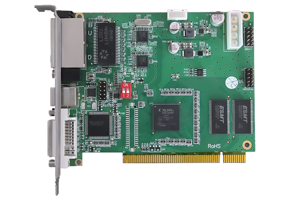
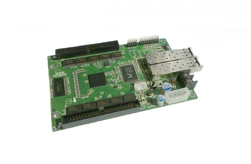
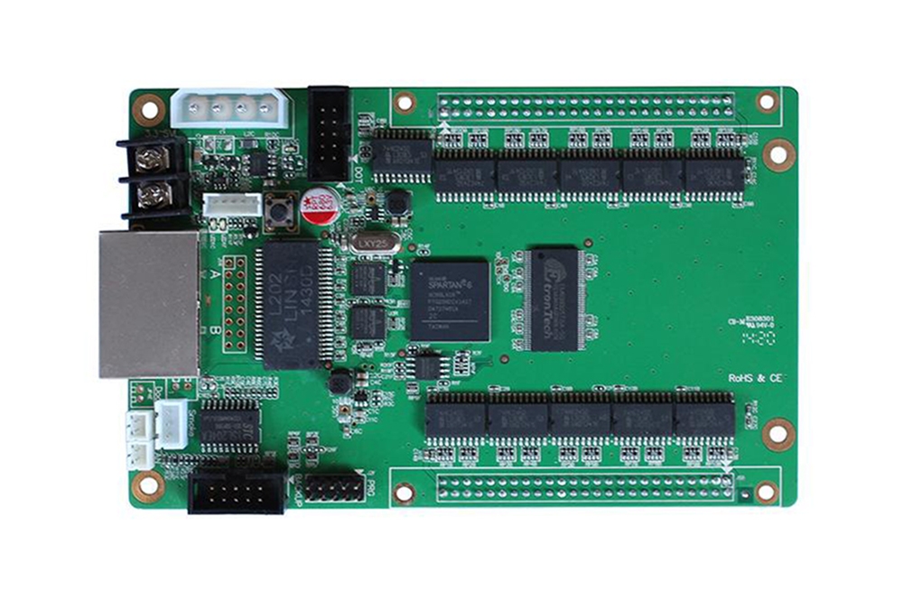
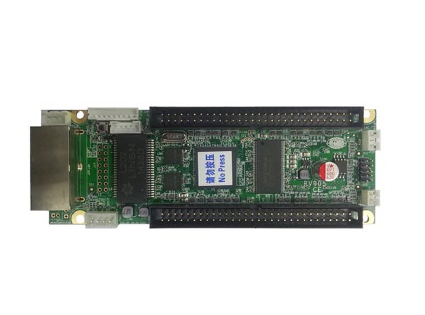
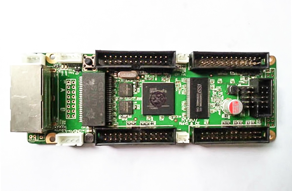
The Mooncell T120 LED receiving card provides 24 RGB data groups for LED display cabinet integration. Review the hardware revision and calibration mode when selecting a replacement or planning a new cabinet.
T120 specifications and revision notes
| Parameter | Specification |
|---|---|
| RGB parallel data | 24 groups |
| Original listing: maximum card / data-group load | 96K pixels / 8K pixels |
| Original listing: input / output grayscale | 8-bit or 10-bit input; up to 20-bit output |
| PDF reference hardware | T120S V1.1; document V3.0 |
| PDF: maximum load | 256 × 384 pixels |
| PDF: brightness / chroma calibration load | 256 × 308 / 256 × 256 pixels |
| Scan support | Original listing: 1–1/32; PDF: 1–64 scan |
| Input voltage | Original listing: +3.5–6 V; PDF: DC 3.5–5.5 V |
| PDF: rated current / power | 0.6 A / 3 W |
| PDF: board dimensions | 70 × 45 mm |
The attached document identifies T120S V1.1 hardware. Its calibration, scan and voltage values differ from the original product description. The table keeps those sources separate so that specifications from different revisions are not combined.
Display configuration and backup
The T120 documentation describes image adjustment and network-cable loop backup. Match the cabinet wiring and saved parameters to the receiving card before commissioning it. Confirm any monitoring or accessory requirements for the supplied hardware.
Frequently Asked Questions
How many RGB data groups does the T120 support?
Both the original listing and linked T120 specification identify 24 RGB parallel data groups. Check the matching connector pinout before integrating the card into a cabinet.
Does calibration reduce the T120 loading capacity?
The original description says calibration does not reduce the load. The linked PDF for T120S V1.1 hardware instead lists 256 × 384 maximum, 256 × 308 brightness-calibrated and 256 × 256 chroma-calibrated loading. Confirm the revision and use its calibration limits.
What supply voltage should I use for the T120?
The original page states +3.5–6 V, while the attached PDF states DC 3.5–5.5 V. Match the supply to the exact hardware label and revision-specific specification; do not assume 6 V is suitable for the documented revision.
Which software configures the receiving card?
The linked specification names AutoLED for layout, rotation, configuration readback and communication checks. Match the module and driver configuration to the installed card.
Can the T120 replace another receiving card without changes?
Check the hardware revision, dimensions, connector pinout, module driver, scan mode and saved configuration first. The listing and PDF contain revision-dependent differences, so the T120 name alone is not enough to establish replacement compatibility.
Product photos and original specification


Download Specification