Quick answer: A quality LED display is not defined by pixel pitch alone. Its performance depends on a complete system of matched LED display components: LED modules, driver ICs, sending and receiving cards, a video processor, power supplies, cabinet structure, cables, cooling and protection hardware. When these parts are correctly specified, tested and integrated, the screen delivers uniform color, stable brightness, smooth video, lower power loss and easier maintenance.
This guide explains what each component does, how it affects image quality and reliability, and what buyers should verify before choosing parts for an indoor or outdoor LED screen.
What Are the Main Components of an LED Display?
An LED display converts a video signal into light through several connected subsystems. The signal path normally runs from a source device to a video processor or controller, then to sending and receiving hardware, driver ICs and finally the LEDs on each module. A separate power path converts AC input into the low-voltage DC power required by the modules and control electronics.
The main LED screen components are:
- LED modules: the display surface containing LEDs, driver ICs and a printed circuit board.
- LED display controller: the sending card, sending box or all-in-one controller that prepares and distributes image data.
- Receiving cards: control individual cabinets or module groups and pass data to the driver circuits.
- Video processor: scales, switches and optimizes input sources for the screen resolution.
- Power supplies: convert mains AC power to stable DC power.
- Cabinet or frame: aligns, protects and supports the modules and internal electronics.
- Hub boards, cables and connectors: distribute data and power between components.
- Cooling and environmental protection: manage heat, moisture, dust and mechanical stress.
LED Display Parts and Their Effect on Quality
| Component | Main function | Quality indicators | Typical signs of a problem |
|---|---|---|---|
| LED module | Produces the visible image | Uniform brightness and color, suitable pixel pitch, consistent LEDs, flat PCB | Dark pixels, color patches, visible seams, uneven brightness |
| Driver IC | Controls current and grayscale for each LED | Stable current, high refresh rate, good low-gray performance | Flicker, scan lines on camera, poor gradients, brightness variation |
| Sending controller | Processes and distributes display data | Correct loading capacity, compatible inputs, reliable configuration | No signal, image tearing, incorrect mapping or resolution |
| Receiving card | Drives modules within a cabinet | Compatible scan mode, calibration support, adequate port capacity | Blank cabinets, repeated sections, color or brightness mismatch |
| Video processor | Scales and switches video sources | Required input formats, output resolution, low latency, image adjustment | Cropped images, soft scaling, delay or unstable source switching |
| LED power supply | Converts AC to regulated DC | Correct voltage, sufficient rated power, efficiency, protection and certification | Random resets, dimming, overheating, shutdown or premature failure |
| Cabinet and mounting system | Maintains alignment and protects parts | Flatness, strength, precise locks, service access and weather rating | Visible gaps, distorted image plane, water entry or difficult maintenance |
| Data and power connections | Carry signals and electrical power | Correct gauge, secure locking, strain relief and clean routing | Intermittent panels, voltage drop, hot connectors or data errors |
1. LED Modules Determine the Visible Image
The LED module is the most visible part of the display, but module quality involves more than the LEDs themselves. Pixel pitch determines viewing distance and image detail; LED package quality affects brightness, color consistency and expected life; the PCB, mask and soldering quality influence flatness, heat transfer and resistance to failure.
Modules used in the same screen should come from compatible production batches and use matching electrical and optical specifications. Mixing modules with different LEDs, driver ICs or calibration data can create obvious color blocks even when the nominal pixel pitch is identical.
What to check on an LED module
- Confirm pixel pitch, module resolution, dimensions, scan mode and operating voltage.
- Inspect the display at full white, primary colors, gray gradients and low brightness.
- Look for dead pixels, uneven color, bright lines, dark corners and module-to-module seams.
- Check the refresh rate and scan performance with a camera if the screen will be filmed.
- Verify that masks, screws, connectors and magnetic or front-service hardware fit securely.
2. Driver ICs Control Refresh Rate, Grayscale and Uniformity
Driver ICs regulate the current supplied to the LEDs and convert receiving-card data into scanning output. Their performance directly affects refresh rate, grayscale depth, low-brightness consistency and camera friendliness. A screen may look acceptable to the eye but show scan lines or flicker on a phone or broadcast camera when the driver configuration is unsuitable.
For studios, stages and filmed events, evaluate the complete module and controller configuration rather than relying on one refresh-rate number. Exposure time, shutter angle, scan ratio, grayscale settings and brightness all influence the final result.
3. The LED Display Control System Keeps Every Cabinet Synchronized
The control system usually includes a sending device and one or more receiving cards. The sending device converts the source image into display data; receiving cards distribute that data to modules and apply parameters such as scan mode, mapping, brightness and calibration coefficients.
Select an LED receiving card according to the cabinet resolution, module interface, loading capacity and control-system ecosystem. For large or high-resolution screens, leave reasonable capacity rather than operating every data port at its absolute limit. Save the final configuration file after commissioning so a replacement card can be restored quickly.
4. A Video Processor Matches the Source to the Screen
LED screens often use non-standard canvas sizes that do not match a source’s native resolution. An LED video processor scales the input to the correct output canvas, switches between sources and may provide cropping, picture-in-picture, color adjustment and backup routing.
Choose a processor with the required HDMI, DVI, SDI, DisplayPort or network inputs, enough output capacity for the total pixels, and latency suitable for the application. Live production and camera-based events require especially careful synchronization and delay testing.
5. Power Supplies Protect Stability and Service Life
A power supply must provide the correct DC voltage and enough continuous power for the connected modules and control hardware. An undersized unit can cause voltage drop, overheating, random cabinet resets or brightness instability. A unit with adequate reserve operates more reliably under changing content and ambient temperature.
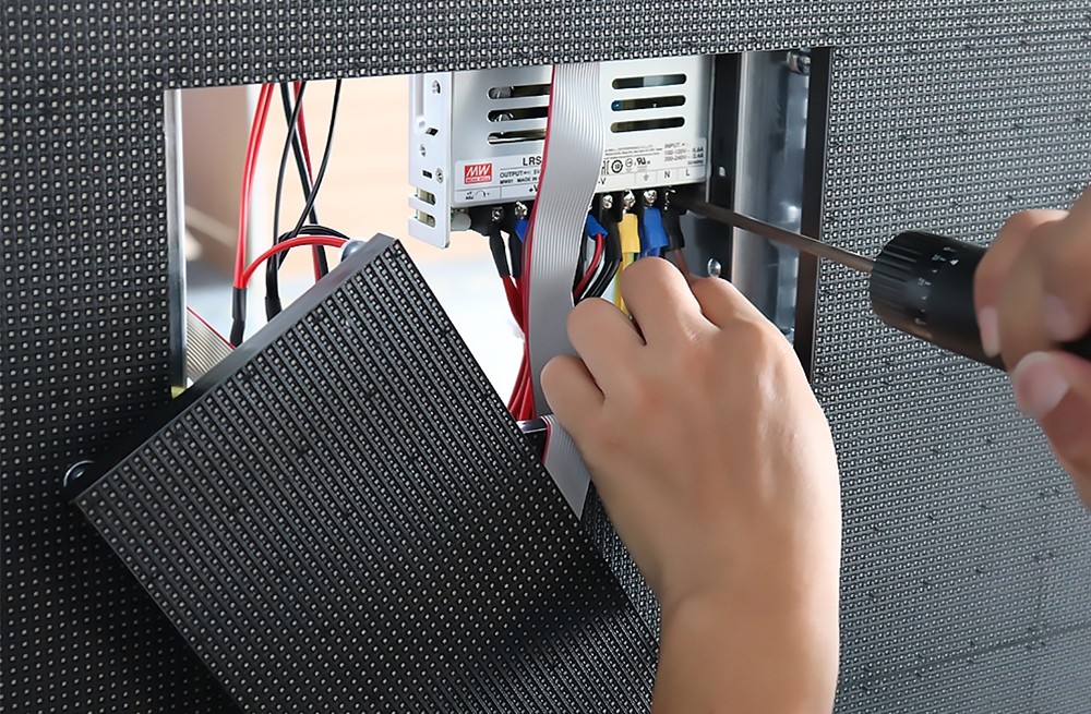
When specifying an LED power supply, check input range, DC output, rated power, efficiency, operating temperature, protection features and relevant certifications. Use balanced power distribution, suitable cable gauge and secure terminals. Grounding and circuit protection should follow local electrical regulations and be completed by qualified personnel.
Why power headroom matters
Full-white content usually creates a higher electrical load than typical video. Design the power system for the screen’s documented maximum demand, environmental conditions and applicable safety margin. Do not estimate capacity from average content alone.
6. Cabinets, Frames and Connectors Preserve Alignment
The cabinet is not just packaging. Its precision determines whether modules form a flat, seamless image plane. Rental cabinets need strong handles, alignment pins and repeated locking accuracy; fixed installations need appropriate load-bearing design and practical front or rear service access.
Outdoor cabinets also require verified ingress protection, drainage, corrosion resistance and temperature control. Gaskets and cable glands must remain correctly seated after maintenance. Even a high-quality module can fail early when moisture enters through a poorly sealed connector or cabinet joint.
How to Verify the Quality of LED Display Components
A specification sheet is the starting point, not the final proof. Buyers should test a representative cabinet or module sample under realistic conditions and keep records for future replacements.
- Confirm compatibility. Match voltage, module interface, scan type, cabinet resolution, control protocol and software version.
- Run an image test. Display red, green, blue, white, black, gray gradients, fine text and moving video.
- Check uniformity. Compare brightness and color across modules and cabinets at both normal and low brightness.
- Test signal stability. Operate the full data path, including backup inputs or redundant links when specified.
- Measure the power system. Check voltage at the power supply and at the farthest module under high load; inspect terminals for abnormal heat.
- Perform a burn-in test. Run varied content long enough to reveal intermittent pixels, thermal issues and unstable connections.
- Inspect serviceability. Confirm that modules, receiving cards and power supplies can be removed without damaging nearby parts.
- Document the configuration. Record model numbers, batch information, firmware, mapping files and calibration data.
Indoor vs. Outdoor LED Display Parts
Indoor and outdoor systems share the same basic architecture, but their priorities differ. Indoor screens emphasize fine pixel pitch, low-brightness grayscale, quiet operation and close viewing. Outdoor screens require higher brightness, environmental sealing, corrosion resistance, thermal management and protection against electrical surges.
| Requirement | Indoor display | Outdoor display |
|---|---|---|
| Brightness | Matched to controlled ambient light | High enough for daylight visibility |
| Protection | Dust control and safe enclosure | Weather sealing, drainage and corrosion resistance |
| Cooling | Often passive or low-noise | Designed for solar load and wide temperatures |
| Pixel pitch | Often finer for short viewing distances | Selected for longer distance and viewing angle |
| Maintenance | Front service is common in wall-mounted installations | Front or rear access depends on structure and weather sealing |
How to Choose Compatible LED Screen Components
Start with the application rather than a brand name. Define the screen dimensions, pixel pitch, viewing distance, content resolution, brightness target, camera requirements, installation environment and service method. Then build a component list in which every interface and capacity is verified.
- Use modules with consistent specifications and batch control.
- Match receiving cards and hub boards to module interfaces and scan parameters.
- Size the controller and processor for the total pixel canvas, inputs and redundancy plan.
- Specify power supplies and wiring for maximum documented load and local voltage.
- Choose cabinets and mounting hardware for the installation’s load, access and protection needs.
- Keep spare modules, receiving cards, power supplies and cables from the same compatible system.
LedControllerCard.com is the online sales department of EagerLED and supplies controllers, receiving cards, video processors, power supplies, modules, cabinets and other LED display parts. Compatibility is more important than selecting any component in isolation, so share your module specifications, screen resolution and intended use when requesting a recommendation.
Frequently Asked Questions
What are the most important components of an LED display?
The essential parts are LED modules, driver ICs, sending and receiving control hardware, a video processor or scaler, power supplies, cabinets, data cables and power distribution. Image quality depends mainly on the modules and drive system, while stability also depends heavily on power, connections, cooling and structural precision.
Which LED display component has the biggest effect on image quality?
The LED module has the most direct effect because it contains the pixels, driver ICs and PCB. However, the final image also depends on controller configuration, calibration, video scaling and power stability. A premium module cannot compensate for incorrect receiving-card parameters or an unstable power system.
How can you verify the quality of LED sign components?
Verify compatibility first, then test full-color patterns, grayscale, text, motion and camera performance. Inspect uniformity, dead pixels, seams and connector temperature. Run a burn-in test under realistic brightness and confirm voltage at the farthest module. Record model, batch, firmware and configuration data for replacements.
Can LED modules from different batches be mixed?
They may operate together when the electrical specifications match, but visible color or brightness differences are common. For a uniform screen, use modules from a controlled compatible batch and retain matching spares. Calibration can reduce some variation but may not fully correct differences in LED packages or aging.
How much spare capacity should an LED power supply have?
The correct reserve depends on the manufacturer’s rating, ambient temperature, wiring, duty cycle and local electrical rules. Size the system from documented maximum demand rather than average video consumption. Avoid continuously operating a power supply at its limit, and verify voltage and temperature during full-white testing.
Do I need a separate video processor?
You need one when the source must be scaled to a non-standard screen canvas, when multiple inputs must be switched, or when features such as cropping, picture-in-picture or backup routing are required. Some all-in-one LED controllers include these functions, so confirm capabilities before adding a separate device.
Final Checklist
A reliable LED display comes from a matched, tested system rather than one impressive specification. Before ordering, confirm component compatibility, test the complete signal and power paths, evaluate image uniformity at realistic brightness, and plan for cooling, environmental protection and service access. For help matching parts to an existing or new screen, contact the LEDControllerCard team with your module model, cabinet resolution, total screen size and input requirements.