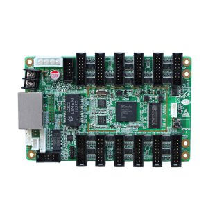
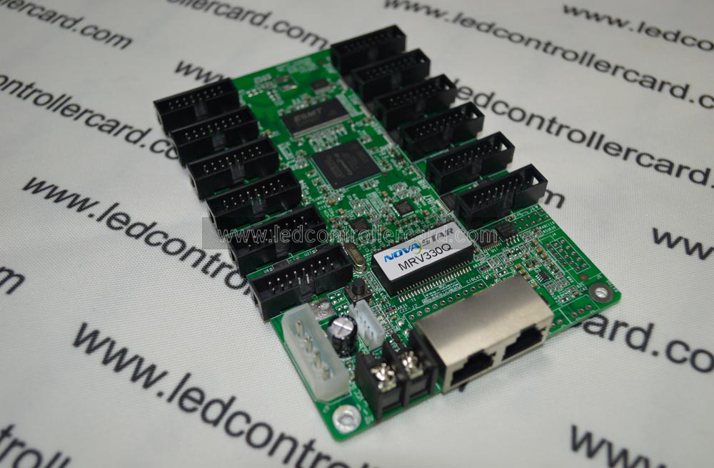
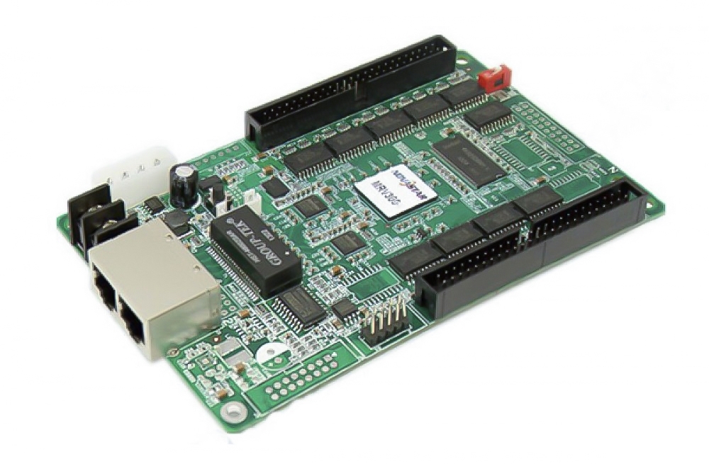
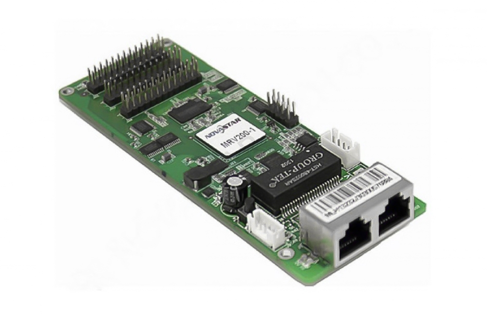
Kystar H7S-C for LED display receiving and cabinet control
The Kystar H7S-C receives data from a compatible LED sending system and converts it into signals for the display driver chips. The model-specific v3.1 document lists 32 parallel data groups and up to 512 × 384 pixels per card, or 196,608 pixels. High-density connectors link the receiving card to the cabinet electronics.
Choose this card by the module interface, driver chip, scan configuration and receiving-card revision. Its pixel load is the cabinet area assigned to one receiver; it is separate from source-video resolution and the sending controller’s total capacity.
Verified H7S-C specifications
| Specification | Details |
|---|---|
| Maximum documented load | 512 × 384 pixels per card |
| Parallel data groups | 32 |
| Module connection | High-density connector interface; verify matching hub-board pinout |
| Supported driver categories | Common driver chips, dual-latch chips and PWM chips; confirm the exact IC |
| Image functions | HDR10, low-brightness grayscale and point-by-point brightness calibration |
| Layout functions | Image rotation and irregular-screen configuration |
| Maintenance functions | Configuration readback, repair and network-status detection |
| Monitoring | Card temperature and voltage |
| Backup functions | Receiving-card backup and dual-power detection with matching wiring |
| Extensions | External LCD module and module-FLASH management with compatible configuration |
| Electrical reference | DC 3.3–5.5V; rated current 0.5A in the referenced document |
Useful display and maintenance features
- Image tuning: use supported color reproduction, HDR10 and calibration workflows.
- Creative cabinet layouts: configure supported rotation and irregular display arrangements.
- Service diagnostics: inspect voltage, temperature and network communication status.
- Card replacement: read back configuration and use the supported repair workflow with the correct parameters.
- Redundancy planning: connect compatible backup receiving cards and the required power-status signals.
Compatibility and configuration limits
The 512 × 384 load is a documented maximum, not a guarantee for every module scan ratio, driver IC or refresh setting. Match the exact connector pinout and signal definitions, then check the desired grayscale and refresh configuration. High-density connectors do not establish compatibility with every hub board.
HDR10 requires a compatible source and sending/receiving workflow. Frequency-doubling and image-tuning features depend on the screen configuration; camera shutter settings also affect captured images. Backup, external LCD and module-FLASH functions require matching equipment and wiring.
The English document’s phrase “dual SIM backup” refers to the receiving-card backup context, including MS_DATA and MS_ID connections; it is not a cellular SIM function. Confirm the complete cabinet backup arrangement before relying on redundancy. For a different receiving-card option, compare the Kystar H8S using its own revision and interface documentation.
Frequently asked questions
How many pixels does one H7S-C carry?
The referenced model document lists up to 512 × 384 pixels, equivalent to 196,608 pixels per card. Actual configuration must fit the module and output settings.
Is H7S-C an LED sending controller?
It is a receiving card installed in the display system. A compatible sending controller and video source are still required.
Can any hub board be used?
No. Match the hub board and module wiring to the H7S-C connector definitions and the exact supplied revision.
Conclusion
H7S-C combines 32 parallel data groups with image-adjustment, monitoring and maintenance tools for a cabinet within the documented load. Select it by the revision, hub pinout, driver IC and scan configuration. Refer to the official Kystar H7S-C v3.1 specification and the preserved download below.


Download Specification:
Kystar H7S-C LED Display Screen Receiver Card Specification