An LED controller pixel load calculator answers a practical question: how many data outputs does your LED wall need? Multiply the wall’s native pixel width by its height, divide by the verified capacity of one output port, and round up. Then check the cabinet arrangement and the rest of the system.
A wall can sit below a controller’s advertised total capacity while overloading an individual port. Input timing, receiving cards and output settings can also invalidate an apparently correct result. The method below turns a pixel count into a port plan you can check before buying equipment or connecting cabinets.
LED Controller Pixel Load Calculator Formulas
Calculate native screen pixels
For a rectangular wall, use:
Total pixels = screen width in pixels × screen height in pixels
With identical cabinets, calculate the wall dimensions first:
Wall width = cabinet columns × cabinet pixel width
Wall height = cabinet rows × cabinet pixel height
Count each full-color image position as one pixel. Do not multiply the result by three for its red, green and blue components.
If you know only physical dimensions and pixel pitch, divide each active dimension in millimeters by the pitch in millimeters to estimate resolution. However, nominal pitch labels can be rounded. Use the actual cabinet or module matrix for the final calculation.
Estimate the minimum active ports
Minimum active ports = round up(total pixels ÷ usable pixels per port)
Here, usable capacity means the applicable limit for your controller, receiving system and output mode. The LED controller pixel load calculator provides an arithmetic minimum; it does not prove that the cabinet layout is supported.
If ports have different capacities, calculate their allocations separately. Keep backup outputs separate from outputs carrying independent sections of the image.
Gather the Inputs Before You Calculate
A reliable LED controller pixel load calculator starts with hardware details, not screen area alone. Two walls with identical physical dimensions can have very different native resolutions.
| Input | What to confirm |
|---|---|
| Wall geometry | Cabinet pixel matrix, cabinet columns and cabinet rows |
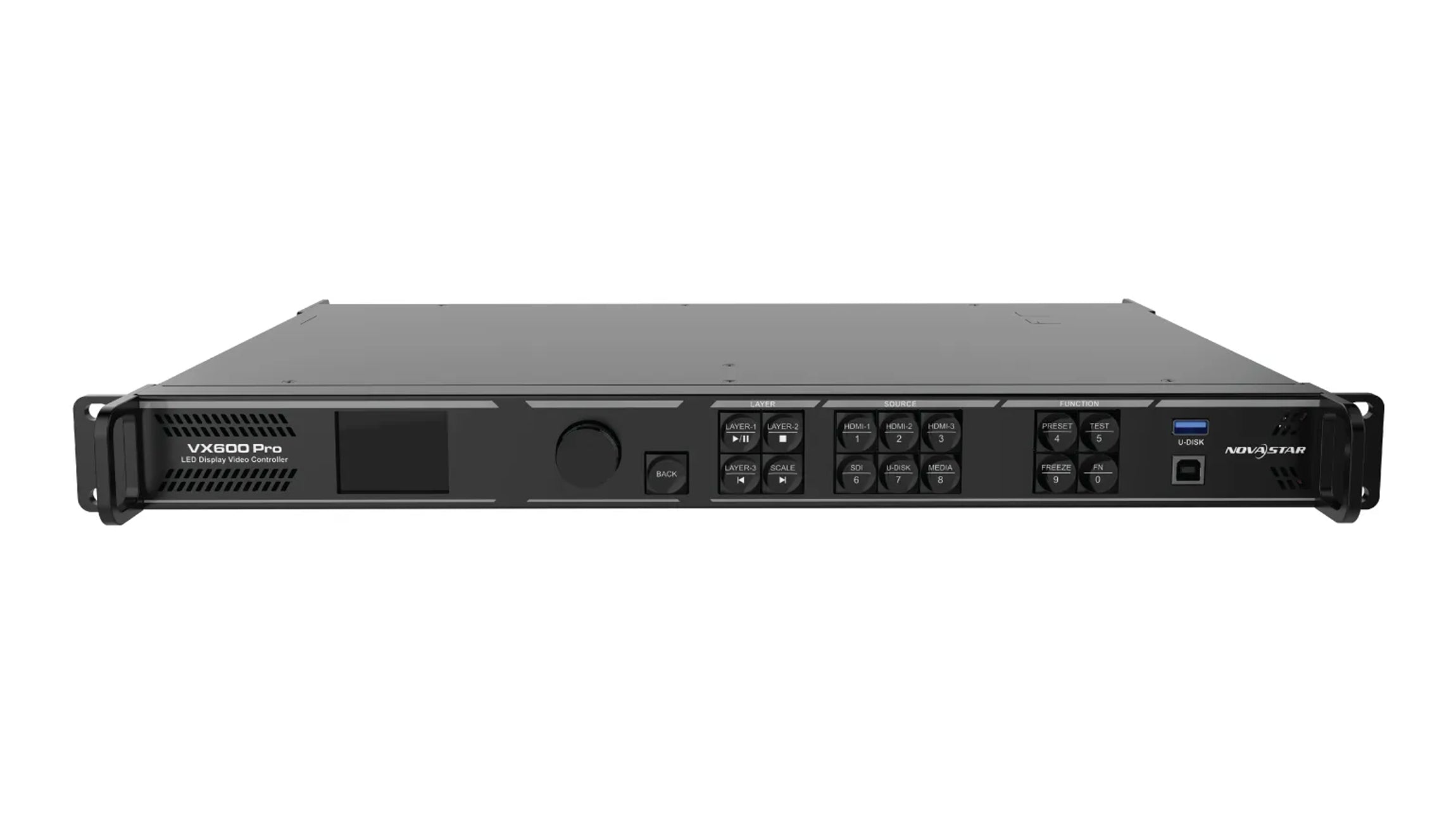
| Controller | Exact model, total pixel capacity and active data outputs |
| Output mode | Frame rate, transmitted bit depth and applicable port capacity |
| Receiving system | Card model, cabinet configuration and supported loading dimensions |
| Backup design | Reserved outputs, copied streams and supported failover topology |
Record the controller firmware and configuration software version with the design. Check the manufacturer’s documentation for that hardware combination, especially when changing output modes or replacing receiving cards.
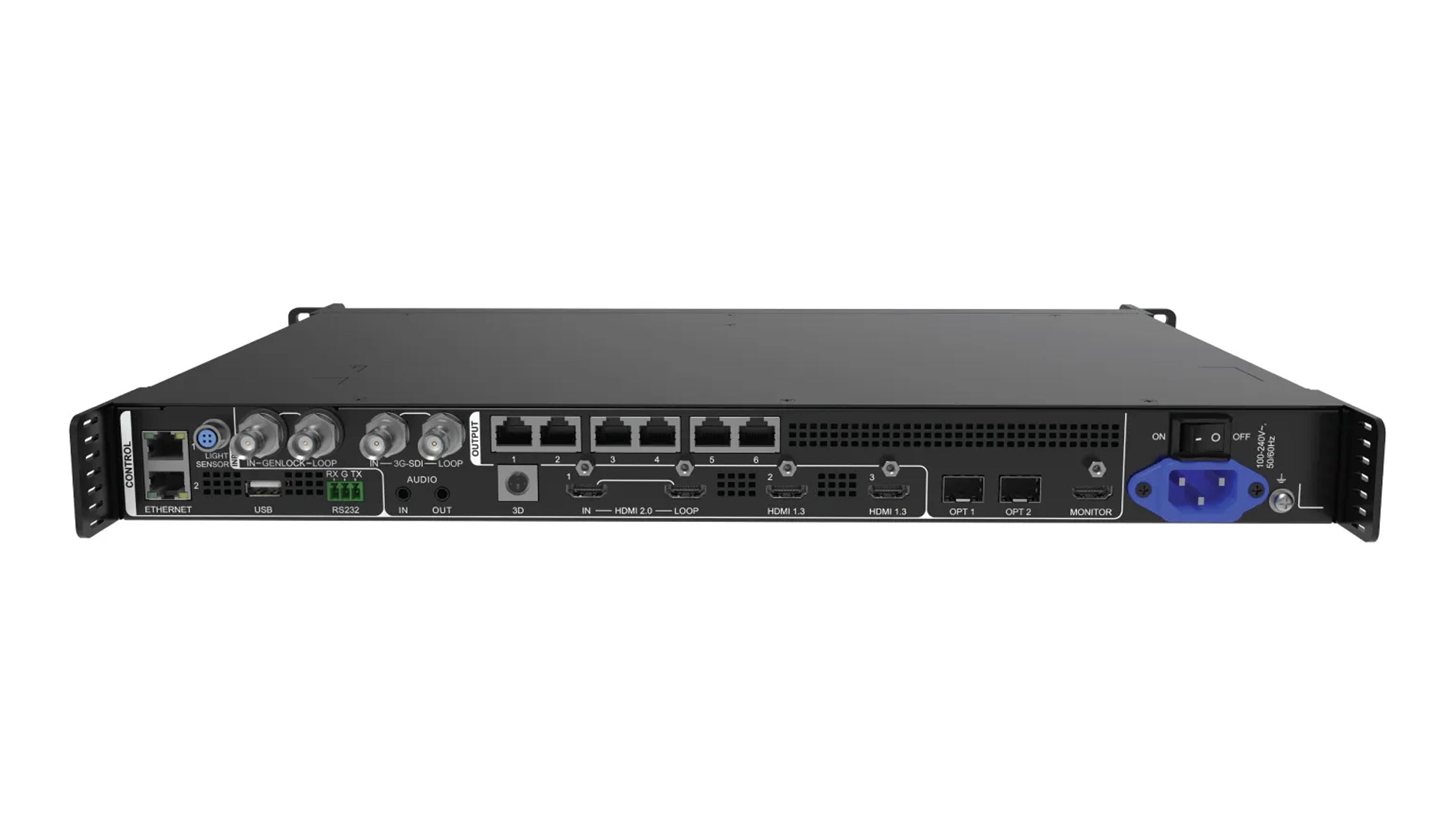
Do not count a control LAN socket as an LED data output. Likewise, an HDMI monitoring output does not automatically become another channel for driving cabinets. Identify connectors by their documented function.
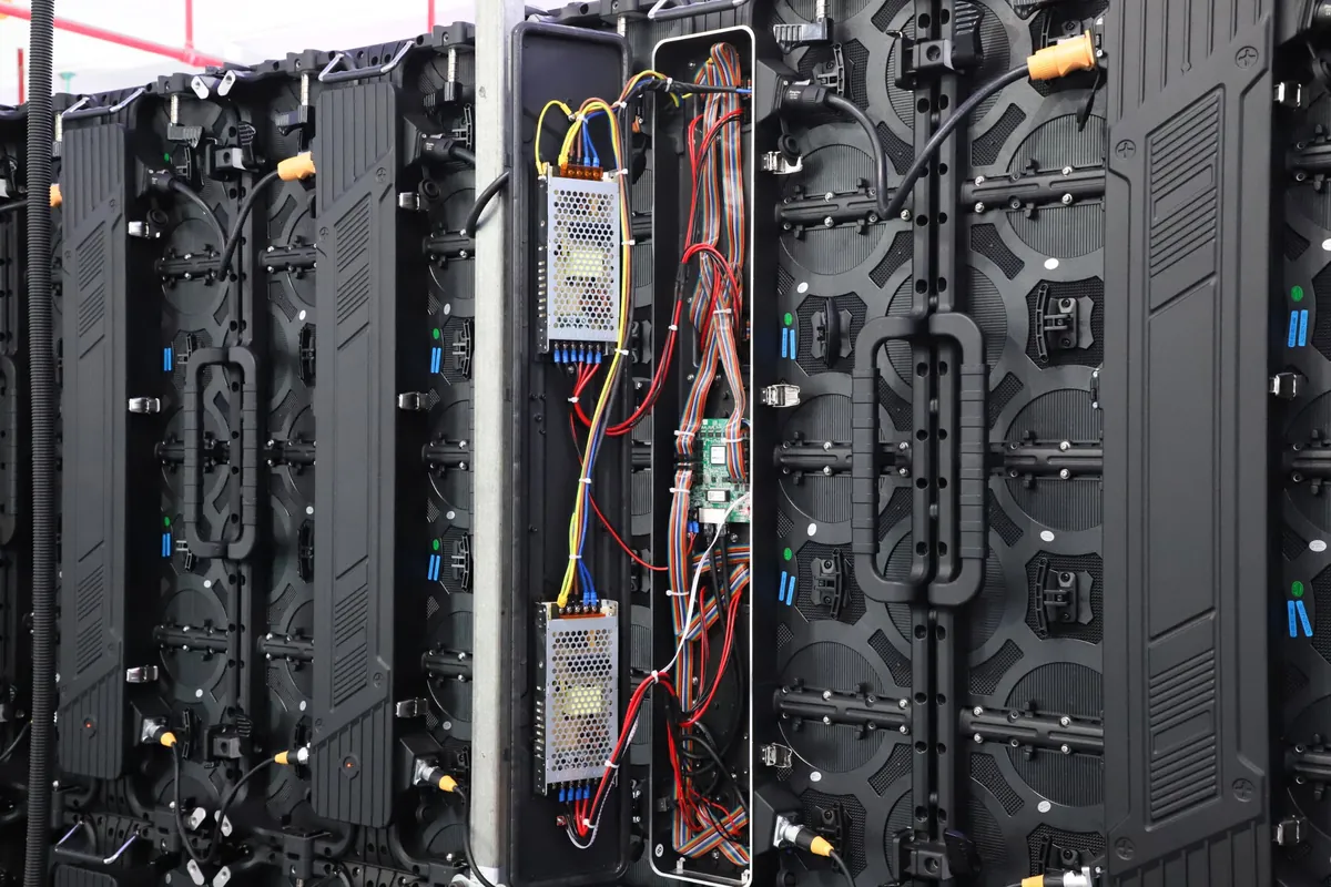
Use the installed modules and receiving electronics as your reference. A replacement cabinet with a different native matrix changes the wall resolution and its port allocation, even when the frame has the same physical dimensions.
Turn Pixel Totals Into a Practical Port Plan
Consider a hypothetical wall containing 10 columns and 6 rows of cabinets. Each cabinet has a native matrix of 192 × 192 pixels:
- Wall resolution: 1,920 × 1,152 pixels.
- Total load: 2,211,840 pixels.
- Assumed usable capacity: 650,000 pixels per active port.
- Arithmetic minimum: round up(2,211,840 ÷ 650,000) = 4 ports.
The 650,000-pixel figure is an illustrative planning input, not a universal Ethernet limit. Replace it with the verified rating for your equipment and output settings.
Divide the wall into whole cabinet groups
Four rectangular groups of 5 × 3 cabinets each would contain 15 cabinets per port. Each group measures 960 × 576 pixels and carries 552,960 pixels. This allocation passes the assumed pixel-count limit, subject to the controller’s mapping and dimensional restrictions.
Each port uses about 85.1% of the assumed capacity, leaving 97,040 pixels unused. That spare capacity belongs to that port; it cannot automatically compensate for another port that is overloaded. This percentage describes the example, rather than a recommended reserve for every project.
For an LED controller pixel load calculator to be useful on site, its output must translate into actual cable routes. Label each group, its starting cabinet and its connection order. Unequal groups are acceptable when every group meets all applicable limits.
Calculate cabinets per port
Whole cabinets per port = round down(usable port capacity ÷ pixels per cabinet)
| Cabinet matrix | Pixels per cabinet | Whole cabinets per port | Assigned pixels |
|---|---|---|---|
| 128 × 128 | 16,384 | 39 | 638,976 |
| 168 × 168 | 28,224 | 23 | 649,152 |
| 192 × 192 | 36,864 | 17 | 626,688 |
| 256 × 256 | 65,536 | 9 | 589,824 |
All rows assume 650,000 usable pixels per port. They describe arithmetic capacity, not guaranteed cabinet-chain configurations.
The LED controller pixel load calculator should round cabinet counts down because a cabinet cannot usually be divided between cables arbitrarily. Receiving-card assignments and the physical design determine the permitted split points.
Check the Limits Behind the Pixel Rating
Total capacity and maximum width or height
Check the controller’s total load independently of each port. Having enough connectors does not guarantee that the processor can address their combined theoretical capacity.
Also check maximum canvas width and height. A listed maximum width and a listed maximum height do not necessarily work simultaneously. Their product may exceed the total pixel capacity. Apply any separate port or receiving-card dimension limits as well.
For a stepped wall or separated screen sections, distinguish the sum of active cabinet pixels from the rectangular area enclosing them. Different mapping systems can account for gaps differently. Check the software’s reported load for the actual arrangement; do not simply subtract empty spaces from a canvas and assume the recovered capacity is available.
Output frame rate and bit depth
An LED controller pixel load calculator must use the capacity for the selected transmitted bit depth and output frame rate. Higher settings can reduce the available load. The reduction depends on the system; a simple proportional bandwidth estimate may not match the supported configuration.
For example, the NovaStar KU20 manual specifies 650,000 pixels per port at 8-bit and 60 Hz. At 10-bit and 60 Hz, it specifies 325,000 pixels, with up to 480,000 when paired with the A10s Pro receiving card. These are KU20-specific conditions, not settings to transfer to another model.
Input bit-depth support also does not establish output loading capacity. Keep video frame rate separate from the panel’s LED refresh frequency: they describe different operations.
Input timing and receiving-card configuration
The input must support the intended resolution and timing. A processor may scale an accepted source onto a differently sized wall, but scaling cannot create additional physical loading capacity.
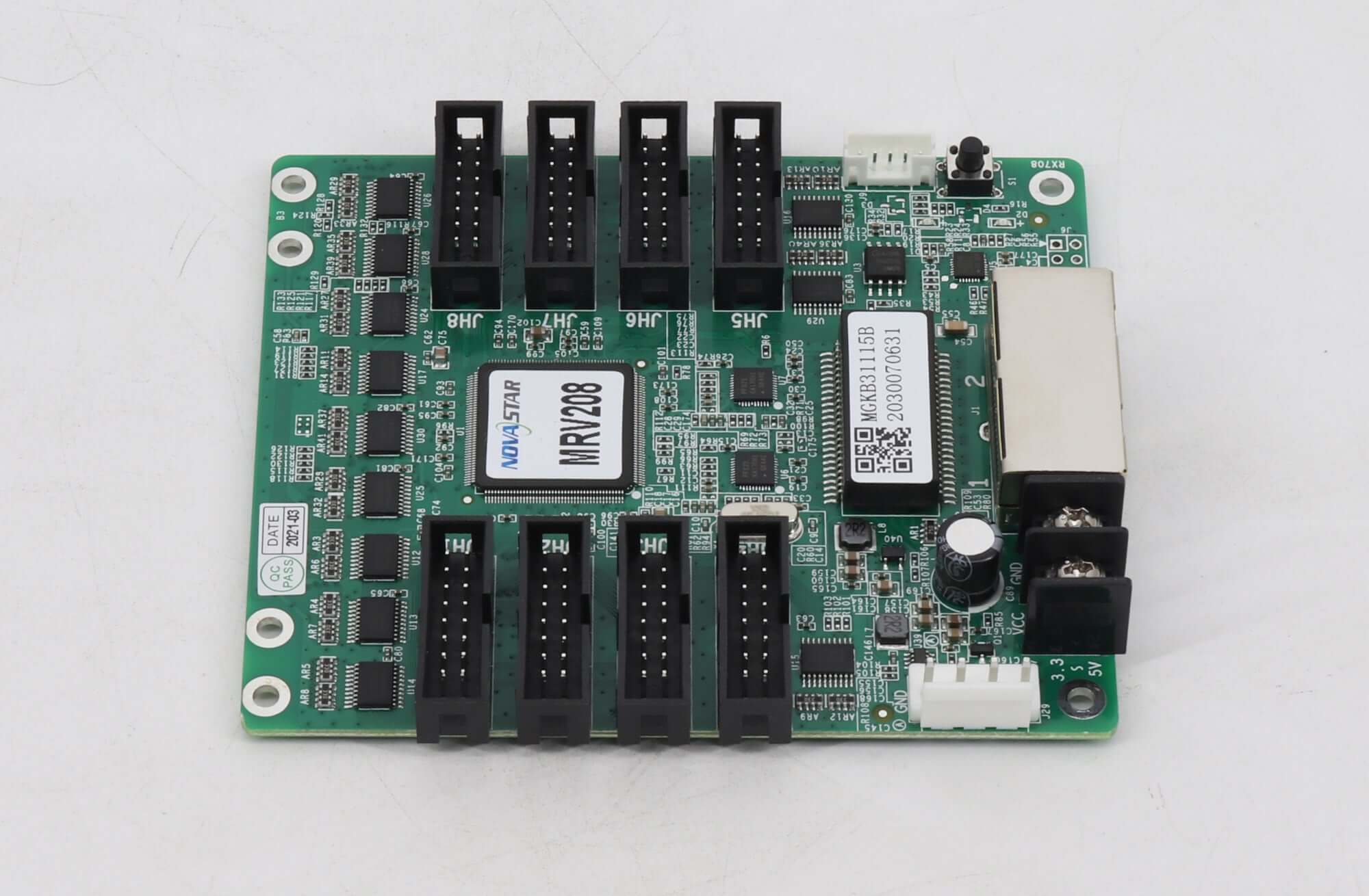
Receiving-card limits introduce another check. A card’s supported dimensions can depend on its driver ICs and configuration. Verify the cabinet file, scan arrangement and card compatibility rather than treating all cards as interchangeable.
Backup and optical output modes
The LED controller pixel load calculator must distinguish independent outputs from copied or backup streams. A fiber connector may transport the same channels already available on copper ports. Its presence alone does not add independent pixels.
Check the documented backup design and the load after a failure. Features such as low latency, rotation or special mapping may introduce further restrictions on particular systems.
Use a Pixel Load Worksheet for Your LED Wall
Use this worksheet to make the LED controller pixel load calculator repeatable. Enter your own native matrix and verified limits before applying the formulas.
| Worksheet item | Hypothetical example |
|---|---|
| Cabinet layout | 10 columns × 6 rows |
| Native cabinet matrix | 192 × 192 pixels |
| Native wall resolution | 1,920 × 1,152 pixels |
| Total wall pixels | 2,211,840 |
| Usable capacity per port | 650,000 pixels, assumed |
| Minimum active ports | 4 |
| Proposed grouping | Four groups of 5 × 3 cabinets |
| Pixels per group | 552,960 |
| Remaining checks | Total capacity, dimensions, input, receivers and backup |
An acceptable average can hide an overloaded cable. If the same 60 cabinets are allocated as 18, 14, 14 and 14, the first port carries 663,552 pixels. It exceeds the assumed 650,000 limit even though the wall still uses four ports.
Redistribute the cabinets within a supported mapping arrangement, or add active capacity if the hardware and geometry require it. Recalculate after every cabinet-count change. Keep project headroom explicit if you choose it; there is no single reserve percentage suitable for every system.
Verify the Layout Before Installation
Treat the LED controller pixel load calculator result as a plan to validate in the configuration software. Match the screen map to the actual cabinet order, then inspect individual output loads and dimensions. Resolve warnings before accepting the design.
Confirm that the source is sending the intended timing and that the configured output mode matches the assumptions. Display a grid or mapping pattern to locate reversed connections, repeated sections and missing cabinets. Then test the intended video content.
If redundancy is required, test the approved failure path and confirm that the remaining connections support the assigned load. Save the working configuration to the appropriate hardware and retain a project copy with port labels and cabinet files. This record makes later troubleshooting and expansion much easier.
Frequently Asked Questions
1. Can an LED controller pixel load calculator estimate electrical power consumption?
No. Pixel load measures image-data capacity. Electrical planning needs the actual cabinet or module power specifications, supply arrangement and operating conditions. Two walls with the same pixel count can draw different amounts of power. Calculate the power distribution separately from the video data plan.
2. Can I connect LED controller outputs through a standard Ethernet switch?
Only when the manufacturer supports that arrangement. An RJ45 connector does not establish compatibility with ordinary network equipment. Some LED systems support specified switches; others require their own distribution hardware or direct connections. Check the LED data network separately from the controller’s management network.
3. Does a fiber converter increase the pixels my controller can drive?
A converter alone does not increase the controller’s processing capacity. It transports the supported streams over a different medium. Confirm how many independent channels the optical link carries and whether any connectors provide copied or backup data rather than additional image areas.
4. Can one output feed cabinets with different pixel resolutions?
Possibly, if the control system supports their receiving cards, configuration files and mapping arrangement. Sum each cabinet’s actual load, then check how the software accounts for mixed fixtures. A pixel-count pass alone does not establish compatibility or ensure consistent image scaling.
5. Will longer Ethernet cables reduce my permitted pixel count?
Do not apply a universal pixels-per-meter deduction. Cable reach, termination quality and signal integrity require separate checks against the approved transmission specification. A connection that exceeds its supported reach needs an appropriate transmission solution, not an assumed reduction in mapped pixels.
6. Can I combine controllers from different brands in one wall?
Do not assume a sender from one brand can drive another brand’s receiving cards. Separate compatible systems can serve different wall sections, but their source mapping, timing and synchronization need deliberate coordination. Confirm the complete signal path before treating them as one display.
7. Can I lower brightness to fix a port overload warning?
Lowering brightness does not remove pixels from the mapped image. Correct the port allocation or choose a supported output mode with sufficient capacity. An LED controller pixel load calculator helps check the allocation, while configuration software identifies the applicable system restrictions.
Conclusion
An LED controller pixel load calculator is most useful when it connects native screen resolution to a workable cabinet map. Calculate the wall pixels, estimate the active ports, and divide the cabinets into supported groups. Then check total capacity, dimensions, output settings, input timing and receiving cards.
Record the controller model, cabinet matrix and operating mode alongside the finished port plan. Verify that plan in software and on the assembled wall before installation. Those checks turn a plausible number into a configuration you can reproduce and maintain.