Quick answer: An LED video wall receiving card is the cabinet-level control board that receives processed display data from an LED sending controller, converts that data into the scan and control signals required by the modules, and keeps the pixels in each cabinet synchronized. Its main purpose is to make the assigned area of an LED screen display the correct image with accurate color, brightness, grayscale, and refresh performance.
This guide explains the purpose and function of an LED receiving card, the features that matter in real installations, and the specifications to check before choosing one. The terms LED receiving card, LED screen receiving card, and video wall receiving card usually refer to the same type of component.
What Is an LED Video Wall Receiving Card?
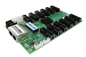
An LED receiving card is installed inside an LED display cabinet. It sits between the sending controller and the LED modules. The sending controller prepares the image data, while the receiving card distributes the correct portion of that data to the modules connected to its output interface or HUB board.
Each receiving card normally controls one cabinet or a defined group of modules. Large video walls use multiple receiving cards connected in a data chain. The control software maps every card to a specific screen position so that all cabinets form one continuous image.
What Is the Purpose of a Video Wall Receiving Card?
The purpose of a video wall receiving card is to translate incoming display data into precise control signals for the LED modules in its assigned cabinet. It handles the final stage of the control path before the driver ICs light the pixels.
In a typical LED display system, the signal moves through these stages:
- A video source sends content to an LED video processor or all-in-one controller.
- The sending controller processes and distributes the screen data.
- Ethernet or optical links carry that data to the receiving cards.
- Each receiving card extracts the data for its mapped area.
- The card sends row, column, color, timing, and brightness control signals to the LED modules.
- The driver ICs activate the red, green, and blue LEDs to reproduce the image.
Key Functions and Features of an LED Receiving Card
1. Data Reception and Distribution
The card receives image data from the sending device and forwards the correct data to its connected modules. Multiple cards can be cascaded so a large LED wall displays one synchronized picture. Supported data ports and redundancy options depend on the card model.
2. Pixel Mapping and Scan Control
The receiving card maps image pixels to the physical module layout. It supports the scan mode, module arrangement, color order, and data-group configuration required by the cabinet. This configuration is often called an RCFG, RCFGX, receiver-card, or cabinet configuration file, depending on the control-system brand.
3. Grayscale, Refresh Rate, and PWM Support
A compatible receiving card works with the module’s driver IC to control grayscale depth, refresh rate, and pulse-width modulation. These factors affect smooth gradients, camera performance, low-brightness image quality, and visible flicker. The final result also depends on the driver IC, scan ratio, module design, controller settings, and frame rate.
4. Brightness and Color Calibration
Many modern receiving cards support brightness calibration and chromaticity calibration. When calibration coefficients are available, the control system can reduce cabinet-to-cabinet differences and improve color uniformity across the LED video wall.
5. Synchronized Display Output
Receiving cards use timing information from the controller so every cabinet refreshes in step. Correct mapping and timing reduce image tearing, misplaced content, repeated sections, and visible seams caused by signal configuration errors.
6. Configuration Storage and Readback
Many cards can store cabinet configuration data and allow it to be read back through the control software. This makes module replacement and maintenance easier, but file formats and readback functions are brand- and model-specific. Do not assume that a configuration file from one control system will work with another.
7. Monitoring and Redundancy
Selected models can report temperature, voltage, communication status, or other cabinet data when used with compatible sensors and software. Some also support loop backup or dual-card redundancy for applications where uninterrupted operation is important. These are optional capabilities, not universal receiving-card features.
Receiving Card Specifications That Matter
| Specification | Why It Matters |
|---|---|
| Maximum load capacity | Defines the maximum width, height, and total pixels the card can control under specified conditions. |
| Supported scan modes | Must match the LED module’s scan ratio and row-decoding method. |
| Data-group outputs | Determines how the card connects to the HUB board or modules. |
| Driver IC compatibility | Affects whether refresh, grayscale, low-brightness, and special adjustment features are available. |
| Color depth and refresh capability | Important for image quality, broadcast use, and on-camera performance. |
| Calibration support | Allows brightness and color correction when calibration data is available. |
| Monitoring and backup | Useful for fixed installations, control rooms, rental systems, and mission-critical displays. |
| Operating conditions | Temperature, humidity, power input, and electrical protection must suit the cabinet environment. |
Important: There is no universal receiving-card pixel capacity. A value such as 326 x 256 pixels may apply to a particular card, scan mode, frame rate, or color-depth setting, but it should not be treated as a standard for every LED receiving card. Always check the current manufacturer datasheet and configuration software.
LED Sending Card vs. Receiving Card
| Component | Main Role | Typical Location |
|---|---|---|
| Sending card or sending controller | Processes the source image and divides it into screen data for transmission. | Inside a controller, processor, computer, or external sending box. |
| Receiving card | Receives its assigned data and drives the connected LED modules through scan and timing signals. | Inside each LED display cabinet. |
A receiving card does not normally decode a compressed video file by itself. Video decoding and scaling are generally handled upstream by the media player, video processor, or all-in-one controller. The receiving card handles the cabinet-level display data.
How to Choose the Right LED Receiving Card
- Match the control-system ecosystem: Confirm compatibility with the sending device and configuration software. Mixing brands is usually not supported.
- Calculate the actual pixel load: Check cabinet width, cabinet height, total pixels, scan ratio, and the manufacturer’s loading rules.
- Verify the module and driver IC: Confirm scan type, HUB interface, data groups, color order, and driver IC support.
- Define image-quality requirements: For broadcast, virtual production, sports, or rental use, prioritize high refresh performance, grayscale quality, and calibration support.
- Plan for reliability: Fixed or critical installations may need status monitoring, loop backup, dual power, or receiving-card redundancy.
- Check mechanical and electrical fit: Compare card dimensions, mounting holes, connectors, supply voltage, and operating temperature.
- Use approved firmware and files: Keep a verified cabinet configuration backup and avoid installing firmware intended for a different model.
You can compare compatible options in our LED receiving card category. If you are building the complete signal chain, also review the available LED sending boxes and LED video processors.
Common Receiving Card Problems
- No image: Check power, data-cable direction, port mapping, controller output, and whether the card is detected by the software.
- Repeated or misplaced image sections: Recheck screen mapping, cabinet resolution, card order, and data-port connections.
- Wrong colors or scrambled rows: Verify the module configuration, color order, scan mode, row decoding, and driver IC settings.
- Flicker or poor camera performance: Review refresh rate, grayscale settings, driver IC capability, clock settings, and content frame rate.
- One cabinet looks different: Check calibration coefficients, brightness settings, module batch, power voltage, and receiving-card configuration.
Frequently Asked Questions
What is the main function of an LED video wall receiving card?
Its main function is to receive display data from the sending controller and convert it into synchronized scan, timing, brightness, and color signals for the LED modules in one cabinet or mapped screen area.
How many receiving cards does an LED screen need?
The number depends on the cabinet design, total resolution, scan ratio, and the maximum load of the selected card. Many cabinets use one receiving card, but high-resolution or unusually shaped cabinets may require more than one.
Can I use any receiving card with any LED controller?
No. The receiving card must be compatible with the sending controller, software, firmware, module interface, and driver IC. Cards from different control-system brands are generally not interchangeable.
Does a receiving card improve LED screen image quality?
It can enable higher refresh rates, better grayscale, calibration, and driver-IC features when the entire system supports them. Image quality is the result of the receiving card, controller, module, driver IC, configuration, and video source working together.
What configuration should be backed up?
Keep a verified copy of the cabinet or receiving-card configuration file, screen mapping, firmware version, calibration data, and any special driver-IC settings. This shortens recovery time after maintenance or replacement.
Final Takeaway
An LED video wall receiving card is the link between the sending controller and the LED modules. Its purpose is to receive the correct part of the image, map it to the cabinet, and generate the precise signals needed for synchronized, accurate display output. Choose a card by confirmed compatibility and real loading requirements rather than by one headline pixel number.
For help matching a receiving card to your LED modules, controller, and cabinet resolution, contact our LED control-system team with the module model, driver IC, scan ratio, cabinet resolution, and sending-device model.