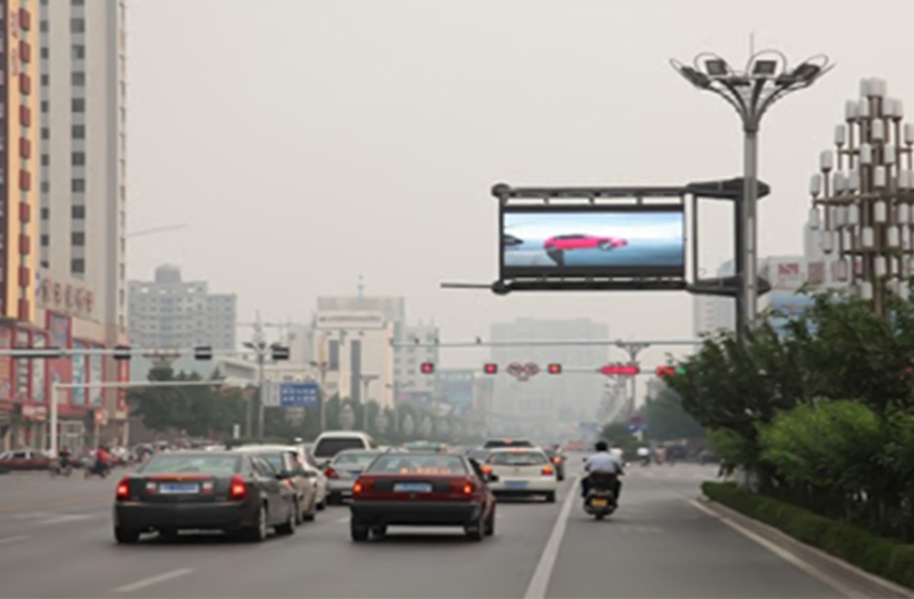
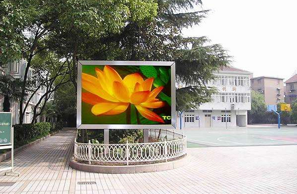
LED screen calibration is the process of measuring and correcting pixel-level differences in brightness and color so that an LED display produces a uniform image. For most installed screens, camera-based on-site calibration is the preferred method because it measures the actual output of every pixel. Runtime-based correction can provide a rough adjustment, but it cannot fully correct uneven LEDs.
This guide explains why LED display correction is needed, compares the main calibration methods, and gives a practical step-by-step workflow for indoor and outdoor LED screens.
What Is LED Screen Calibration?
LED screen calibration, also called LED display correction or uniformity calibration, adjusts the red, green, and blue output of individual pixels or modules. The objective is to make the screen look consistent across its entire surface, without visible bright spots, dark patches, color blocks, or seams.
Calibration data is normally stored in the LED control system and applied through the sending card and receiving cards. The process changes the drive values used for each pixel; it does not physically repair a failed LED, a damaged module, or a faulty power supply.
Why Does an LED Display Need Correction?
Even LEDs from the same production batch do not have perfectly identical optical characteristics. Differences become more visible after installation because operating hours, temperature, moisture, dust, replacement modules, and power conditions affect each area differently.
- Brightness decay: LEDs gradually lose output, but not at exactly the same rate.
- Color shift: red, green, and blue LEDs age differently, changing white balance and color temperature.
- Module replacement: a new module may be brighter or have a different color response than older modules.
- Environmental variation: heat, sunlight, ventilation, and contamination can create uneven aging across the cabinet.
- Manufacturing tolerances: small differences in LED bins, driver ICs, masks, and power distribution can be visible on large screens.
Common symptoms include a grainy image, patchy brightness, color blocks, visible cabinet boundaries, inconsistent gray levels, and a mosaic effect on low-brightness content.
LED Display Calibration Methods Compared
| Method | How it works | Best use | Main limitation |
|---|---|---|---|
| Factory calibration | Measures modules or cabinets before shipment under controlled conditions. | New displays and matched production batches. | Does not account for aging or the final installation environment. |
| Runtime-based correction | Estimates brightness decay from recorded operating hours. | Temporary adjustment when measurement equipment is unavailable. | Cannot measure the real output of individual pixels. |
| Module or cabinet matching | Adjusts replacement sections to resemble adjacent areas. | Repairs and partial module replacement. | May leave pixel-level non-uniformity. |
| Camera-based on-site calibration | Measures the optical output of pixels and generates correction coefficients. | Installed indoor and outdoor LED displays. | Requires compatible software, equipment, and controlled test conditions. |
Method 1: Runtime-Based LED Correction
Runtime-based correction records how long each module has operated and uses an estimated aging curve to reduce differences between sections. It is convenient and usually requires little manual work.
However, operating time is only an indirect indicator. Two LEDs with the same runtime can have different brightness because of temperature, drive current, component tolerances, or local environmental conditions. This method also cannot accurately measure individual pixels. As a result, it may reduce a large brightness difference while leaving a visible mosaic pattern.
Use runtime-based correction as a temporary maintenance tool, not as a substitute for optical measurement.
Method 2: Camera-Based On-Site Calibration
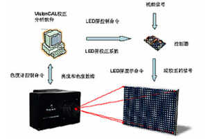
Camera-based calibration measures the actual luminance and chromatic response of the display. Calibration software compares each measurement with a target value, calculates correction coefficients, and sends those coefficients to the LED control system.
This is the most effective method for restoring uniformity on an installed screen because it corrects measured differences rather than estimated aging. Depending on the control system and equipment, calibration may be performed by module, cabinet, region, or individual pixel.
How to Calibrate an LED Screen Step by Step
- Inspect and repair the display. Replace failed LEDs, loose cables, damaged modules, unstable power supplies, and faulty receiving cards before calibration. Calibration cannot compensate for hardware failure.
- Warm up the screen. Allow the display to reach a stable operating temperature. Keep the test conditions consistent throughout measurement.
- Prepare the environment. Reduce ambient light where possible, avoid reflections, and position the camera perpendicular to the screen. For outdoor displays, stable low-light conditions are usually easier to control.
- Set the baseline. Confirm the screen resolution, scan configuration, refresh rate, brightness level, color temperature, and gamma. Do not change these settings during measurement.
- Measure RGB output. Show the required red, green, blue, white, and gray test patterns. The camera or colorimeter records pixel or module output.
- Generate and upload coefficients. The calibration software calculates the correction values and writes them to the compatible control system. Back up the original and new calibration files.
- Verify with real content. Check white, primary colors, gray gradients, skin tones, and low-brightness video from several viewing distances. Repeat measurement if blocks or seams remain visible.
Equipment and Conditions You Need
- A calibration camera, imaging colorimeter, or supported measurement device
- Calibration software compatible with the LED control system
- Access to the sending device and receiving card configuration
- A stable tripod and a clear, centered view of the full calibration area
- Standard RGB, white, and grayscale test patterns
- Stable power, temperature, brightness, gamma, and ambient-light conditions
Before starting, confirm that the controller and receiving cards support coefficient storage and the required calibration workflow. If a video processor is in the signal path, keep its scaling and color settings fixed during the measurement.
Brightness Calibration vs. Color Calibration
Brightness calibration makes pixel luminance more uniform. It is the priority when the screen shows obvious light and dark patches. Color calibration aligns RGB output so that whites, grays, and colors appear consistent across modules and cabinets.
The two processes are related. A screen can have uniform brightness but still show color blocks, or accurate color in one area but inconsistent luminance across the display. A complete calibration normally addresses both.
When Should an LED Display Be Recalibrated?
There is no universal calendar interval. Calibrate based on visible performance and operating conditions. An inspection is recommended after replacing modules or cabinets, changing major control hardware, moving a rental display, or noticing brightness and color differences.
High-use outdoor screens may need checks more often than lightly used indoor screens because heat, sunlight, and weather accelerate uneven aging. Keep previous calibration files and maintenance records so changes can be compared over time.
Common Calibration Mistakes
- Calibrating before failed LEDs, power problems, or data faults are repaired
- Changing brightness, gamma, or processor settings during measurement
- Allowing strong ambient light or reflections to affect the camera
- Using an incorrect screen configuration or loading coefficients into the wrong receiving cards
- Matching only module brightness without checking pixel-level color uniformity
- Skipping a backup of the original configuration and calibration data
- Judging the result with a single white test image instead of grayscale and real video
Frequently Asked Questions
Can software alone calibrate an LED screen?
Software can calculate and apply correction values, but accurate pixel-level calibration requires measured optical data from a compatible camera or colorimeter. Software based only on runtime estimates cannot see the actual brightness and color of each LED.
Can calibration fix dead pixels or a damaged module?
No. Hardware faults must be repaired first. Calibration can reduce measurable brightness and color differences in working pixels, but it cannot restore a failed LED, unstable power supply, damaged driver IC, or broken signal path.
Does calibration reduce maximum brightness?
Usually, yes. Uniformity is achieved by bringing brighter pixels down toward a common target; weak pixels cannot be driven beyond their safe capability. The target should balance uniformity with the brightness required for the installation.
Why do replacement LED modules look different?
A replacement module may use a different LED bin, mask, driver IC, production batch, or number of operating hours. Module matching and on-site calibration can reduce the difference, but a closely matched spare module provides the best starting point.
What is the best correction method for an installed LED display?
For most working installations, camera-based on-site calibration is the best method because it measures the actual output of the screen and can correct brightness and color at pixel or module level. Runtime-based correction is less precise and is better used as a temporary adjustment.
Final Recommendation
Start with hardware inspection, stabilize the display settings and environment, then use camera-based on-site calibration whenever accurate uniformity is required. Maintain backups of the screen configuration and correction coefficients, and verify the result with grayscale patterns and real content.
For help choosing compatible LED control hardware or planning a calibration workflow, contact LED Controller Card with your screen size, pixel pitch, controller model, receiving card model, and photos of the uniformity problem.
This article was written by Yudong and updated by the LED Controller Card technical team.