This LED display controller guide shows how a controller receives video, converts it into the LED wall’s pixel canvas, and distributes data through sending outputs to receiving cards and LED modules. Correct sizing means checking the complete signal path, not just comparing total pixels. The controller, individual output ports, receiving cards, input formats, frame rate, bit depth, topology, and redundancy plan must all support the intended system.
This LED display controller guide explains that process step by step. It includes practical formulas, a worked sizing example, selection criteria, and a commissioning checklist for integrators, rental technicians, buyers, and project engineers.
How do you size an LED display controller?
Use this sequence:
- Calculate the LED wall’s exact pixel width and height.
- Multiply them to find the total pixel load.
- Calculate each cabinet’s pixel resolution and cabinet count.
- Divide cabinets into practical, contiguous regions for the controller’s output ports.
- Verify both the total controller capacity and the load, maximum width, and maximum height allowed on every port.
- Check input resolution, frame rate, color depth, HDR, latency, fiber distance, synchronization, and redundancy requirements.
- Select receiving cards and HUB connections that match the module scan type and required output groups.
A useful engineering target is to keep normal port loading below about 80% of the published limit where the project allows it. This 20% margin is a practical design recommendation, not a universal manufacturer rule. It gives the mapping some flexibility and reduces the risk that a later change in bit depth, refresh mode, or cabinet arrangement will exceed a limit.
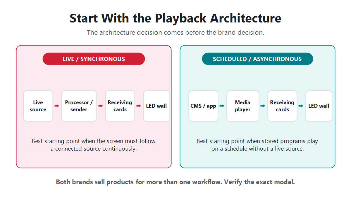
LED display controller guide to signal flow
A reliable design starts with the entire chain:
Video source -> processor or scaler -> sending controller -> Ethernet or fiber transport -> receiving card -> HUB board -> LED modules.
1. Video source
The source may be a computer, media server, camera system, switcher, or media player. Before choosing a controller, record the source connector, resolution, refresh rate, color format, color depth, and whether HDCP-protected content is involved. A controller with enough LED pixels can still be unsuitable if it cannot accept the required input format.
2. Video processor or scaler
The processor scales, crops, switches, and composites sources into the canvas sent to the LED system. Some products combine processing and sending in one chassis; others use a separate LED video processor and sending device. Define where scaling occurs so that operators do not accidentally scale the image twice.
The output canvas normally matches the mapped LED area. For a 2400 x 1400-pixel wall, a 2400 x 1400 custom output provides a direct 1:1 relationship. A standard 3840 x 2160 canvas can also carry the wall as a region, but the mapping and unused pixels must be planned.
3. Sending controller
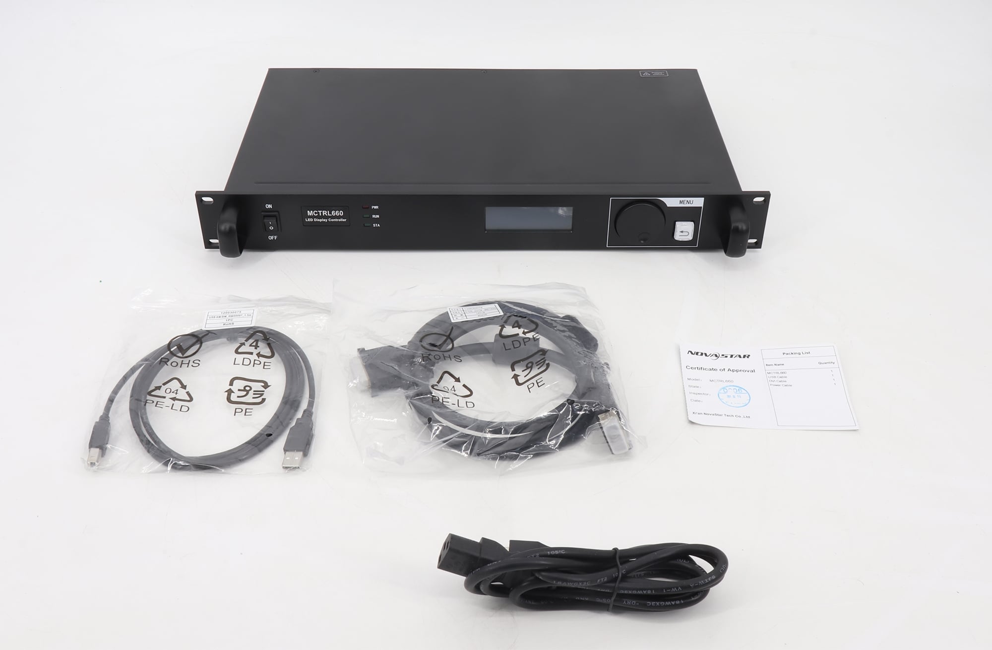
The sending controller converts the processed canvas into the data format used by the LED receiving system. Its key limits include total pixel capacity, capacity per output, maximum load width and height, supported frame rates, bit depth, low-latency modes, synchronization, and backup behavior.
Do not treat total pixel capacity as the only pass/fail number. A controller may have enough aggregate capacity while an individual Ethernet output is overloaded or a mapped strip exceeds a maximum dimension.
4. Ethernet or fiber transport
Controller outputs usually feed cabinet chains over network cable; fiber converters or optical outputs extend distance and improve isolation for large venues. Keep each port’s cabinets in a continuous rectangular region whenever possible. A simple topology is easier to map, test, document, and recover than a chain that jumps repeatedly across the wall.
For critical installations, use supported primary and backup signal paths. Redundancy must be configured and tested; adding a spare cable alone does not create automatic failover.
5. Receiving card
The LED receiving card accepts cabinet data and drives the module interface through a HUB board or integrated connectors. Its usable load is constrained by pixel capacity, maximum width and height, parallel RGB groups, scan type, gray scale, refresh rate, and the cabinet’s electrical design.
One receiving card per cabinet is common, but it is not a rule. Small cabinets may share a card, while high-resolution or complex cabinets may require multiple cards. Size the receiving system from the actual cabinet map and card specification.
6. HUB board and LED modules
The HUB board routes power and data between the receiving card and modules. Pinout, scan configuration, driver IC, data-group count, module orientation, and ribbon-cable order must match the cabinet configuration file. Incorrect settings can produce shifted rows, repeated content, color errors, flicker, or a blank section even when controller sizing is correct.
LED controller sizing formulas
Step 1: Convert physical dimensions to pixels
If the active width and height divide evenly by the pixel pitch:
Pixel width = active width in millimeters / pixel pitch in millimeters
Pixel height = active height in millimeters / pixel pitch in millimeters
Total pixels = pixel width x pixel height
Use the module or cabinet’s documented pixel resolution for final design. Nominal pitch and nominal cabinet size can be rounded, so dividing millimeters by pitch is best for early estimates, not final commissioning data.
Step 2: Calculate cabinet resolution
Cabinet pixel width = modules across x module pixel width
Cabinet pixel height = modules high x module pixel height
Pixels per cabinet = cabinet pixel width x cabinet pixel height
Then calculate cabinet quantity:
Cabinets across = wall pixel width / cabinet pixel width
Cabinets high = wall pixel height / cabinet pixel height
Step 3: Size each output port
For each proposed port chain:
Port pixel load = sum of all cabinet pixels on that port
The result must remain within every applicable controller limit. Check:
- maximum pixels per port;
- maximum mapped width per port;
- maximum mapped height per port;
- per-port limits at the selected bit depth and frame rate;
- maximum number of receiving cards or cascade length, if specified;
- the physical cable route and service access.
Published values such as 650,000 pixels on a Gigabit output are common reference points in some controller ecosystems and modes, but they are not universal. Always use the datasheet and software constraints for the exact model and operating mode. For NovaStar hardware, obtain current manuals and specifications from the manufacturer’s official download center.
Step 4: Size the complete controller
Required controller pixels = sum of all active LED pixels
Choose a controller whose total capacity exceeds this number and that has enough usable outputs for the port plan. The number of required outputs is determined by both bandwidth and topology. A wall that fits within four ports mathematically may need six ports to create clean cabinet regions or support redundancy.
Step 5: Count receiving cards
Begin with the cabinet design rather than assuming one card per cabinet:
Receiving cards required = cabinets x receiving cards per cabinet
Then confirm that each card’s assigned pixel rectangle, data groups, module count, and scan configuration are supported. For more background, see this guide to LED receiving card functions and features.
Worked example: 6 m x 3.5 m P2.5 LED wall
Assume the display uses 500 x 500 mm cabinets and each cabinet is 200 x 200 pixels.
| Calculation | Formula | Result |
|---|---|---|
| Wall pixel width | 6000 / 2.5 | 2400 px |
| Wall pixel height | 3500 / 2.5 | 1400 px |
| Total pixel load | 2400 x 1400 | 3,360,000 px |
| Cabinets across | 6000 / 500 | 12 |
| Cabinets high | 3500 / 500 | 7 |
| Total cabinets | 12 x 7 | 84 |
| Pixels per cabinet | 200 x 200 | 40,000 px |
A clean port plan assigns one 12-cabinet row to each output:
12 cabinets x 40,000 pixels = 480,000 pixels per port
Seven rows therefore require seven outputs. If the chosen controller is rated for 650,000 pixels per output in the intended mode, each output has approximately 26% spare capacity:
(650,000 – 480,000) / 650,000 = 26.2%
The selected controller must support at least 3.36 million total pixels, at least seven usable outputs, and a 2400 x 1400 overall canvas. It must also accept the source format and support the required frame rate, bit depth, mapping dimensions, latency, and backup scheme.
Why pixel count alone can produce the wrong controller choice
| Constraint | What to verify | Failure if ignored |
|---|---|---|
| Input format | Connector, resolution, frame rate, HDCP | No signal or fallback resolution |
| Canvas dimensions | Maximum input/output width and height | Canvas cannot be created |
| Port load | Pixels and mapped dimensions per output | Port overload or incomplete image |
| Color processing | Bit depth, HDR, color space | Banding, incorrect color, reduced capacity |
| Synchronization | Genlock, frame lock, multi-controller sync | Visible tearing between sections |
| Latency | Processing delay in every stage | Lip-sync or camera delay |
| Transport | Copper distance, fiber type, optical modules | Intermittent or lost data |
| Redundancy | Supported loop, backup port, controller backup | No automatic recovery |
Which type of LED display controller should you use?
| Controller type | Best fit | Main sizing focus |
|---|---|---|
| Synchronous sending controller | Live events, studios, control rooms, high-quality real-time video | Input format, total pixels, port plan, latency, synchronization |
| All-in-one video controller | Systems that need switching, scaling, processing, and sending in one device | Input/output layers, canvas size, total pixels, operator workflow |
| Asynchronous controller or media player | Signs and scheduled content that can play without a live source | Storage, decoding resolution, connectivity, schedule features, LED load |
| Multi-controller system | Very large, high-frame-rate, redundant, or unusually shaped walls | Synchronization, canvas division, routing, backup, unified control |
Browse LED sending boxes and compare their published loading limits with the completed port map. For mixed-source systems, also review the video wall processor guide.
Special sizing cases
High frame rate, HDR, or high bit depth
Higher frame rates and deeper color can increase bandwidth or reduce the maximum pixels available in a particular mode. Confirm the combined operating point, not separate maximum claims taken from different test conditions.
Ultra-wide or ultra-tall LED walls
A narrow banner may have a modest total pixel count but exceed an output’s maximum width. Split the canvas into supported regions and verify how the controller software treats custom resolutions.
Irregular and creative LED displays
Curves, corners, columns, ribbons, and separated sections often need extra outputs because rectangular data regions contain unused space or because cable routes cannot follow the visual canvas. Draw both a logical pixel map and a physical cable map.
Long-distance links
Use supported fiber converters or optical outputs when copper distance, electrical isolation, venue infrastructure, or reliability requires them. Match fiber type, wavelength, connectors, and optical modules at both ends.
Redundant systems
Calculate primary and backup capacity separately. A backup controller or port must be able to carry the intended load after failure. Include backup power and network paths where the project risk assessment requires them.
LED display controller selection checklist
- Exact active pixel width, height, and total pixels
- Module and cabinet pixel resolution
- Cabinet quantity and orientation
- Receiving cards per cabinet and supported scan configuration
- Port-by-port cabinet map and pixel load
- Total controller capacity and number of usable outputs
- Maximum width and height per port
- Required input connectors, resolution, refresh rate, and HDCP support
- Color depth, HDR, calibration, and refresh requirements
- Acceptable end-to-end latency
- Copper and fiber distances
- Genlock or multi-controller synchronization
- Primary and backup signal topology
- Configuration software and firmware compatibility
- Spare ports, spare receiving cards, and service access
Commissioning checks before handover
- Load the correct receiving-card and cabinet configuration from a known-good file.
- Confirm the input format and test the exact production frame rate.
- Verify every output’s mapped width, height, pixel count, and cabinet order.
- Run solid red, green, blue, white, black, gray ramps, and motion patterns.
- Check seams, orientation, color, brightness, flicker, dropped data, and temperature.
- Measure or verify latency if cameras, audio, or interactive content are involved.
- Disconnect the primary signal and power paths one at a time to prove redundancy.
- Save the final configuration, port map, firmware versions, and cable labels.
The controller is only one part of the system. Module quality, power distribution, thermal design, grounding, cabinet construction, and cabling also affect reliability. See the overview of LED display components and their functions.
Frequently asked questions
How many pixels can an LED display controller handle?
The limit is model- and mode-specific. Check total loading capacity, pixels per output, maximum output width and height, and any reduced limits at higher frame rates or bit depths. Use the lowest applicable limit.
How many receiving cards does an LED wall need?
It depends on cabinet resolution, module layout, scan type, data groups, and the receiving card’s load limits. One card per cabinet is common, but some cabinets share a card and others require two or more.
Does pixel pitch determine controller size?
Pixel pitch affects the pixel resolution of a given physical area, but controller sizing uses the final pixel width, height, and total load. Two walls with the same physical dimensions can require very different controllers when their pitches differ.
Is an LED video processor the same as an LED controller?
Not always. A processor scales and switches video; a sending controller distributes the LED data. Many all-in-one devices combine both functions, so confirm the product architecture and where each function occurs.
Why should cabinets on one port form a continuous region?
Contiguous regions simplify mapping, cabling, troubleshooting, backup planning, and documentation. Discontinuous mapping can work in some systems, but it increases operational risk and makes faults harder to isolate.
How much spare controller capacity is recommended?
About 20% spare capacity is a useful planning target when budget and topology allow it. It is not a universal requirement. Critical systems may need more reserve, while tightly constrained installations may operate closer to published limits after full verification.
Final recommendation
Choose an LED display controller only after completing the source-to-module signal diagram and a port-by-port load map. Verify the exact specifications for the selected model, keep practical headroom, and test the real operating mode before installation. For help matching a controller, receiving cards, and processing hardware to a specific pixel map, contact the LED Controller Card team with the wall dimensions, pixel pitch, cabinet resolution, source format, frame rate, and redundancy requirements.