A reliable Colorlight 5A-75B setup starts with the module specification and ends with a successful restart. Check power and signal wiring, detect the hardware, configure one receiving card, map the cabinets, then save and verify the result. Following this sequence helps separate wiring faults from parameter errors.
The receiving card converts display data into signals for the LED modules. The sending device supplies that data, while configuration software defines how the modules and cabinets display it. This checklist covers commissioning and replacement work.

1. Before You Start Your Colorlight 5A-75B Setup
Read the model and revision printed on the board. Obtain the module supplier’s parameter file and record the driver IC, decoder IC where applicable, scan ratio, and pixel dimensions. Pixel pitch alone cannot identify these settings. Photograph existing cable positions before disconnecting anything.
For an operating screen, read back and export the working configuration before making changes. Keep receiver parameters, screen mapping, and calibration backups clearly identified; one file should not be assumed to contain everything.
| Check | Required information | Pass condition |
|---|---|---|
| Hardware | Card revision and module ICs | Exact hardware identified |
| Module | Pixel dimensions and scan ratio | Supplier settings available |
| Wiring | HUB75 pinout and cable route | Connections match the design |
| Backup | Parameters, mapping, calibration | Original files safely retained |
| Load | Pixels per receiver and sender port | Within verified system limits |
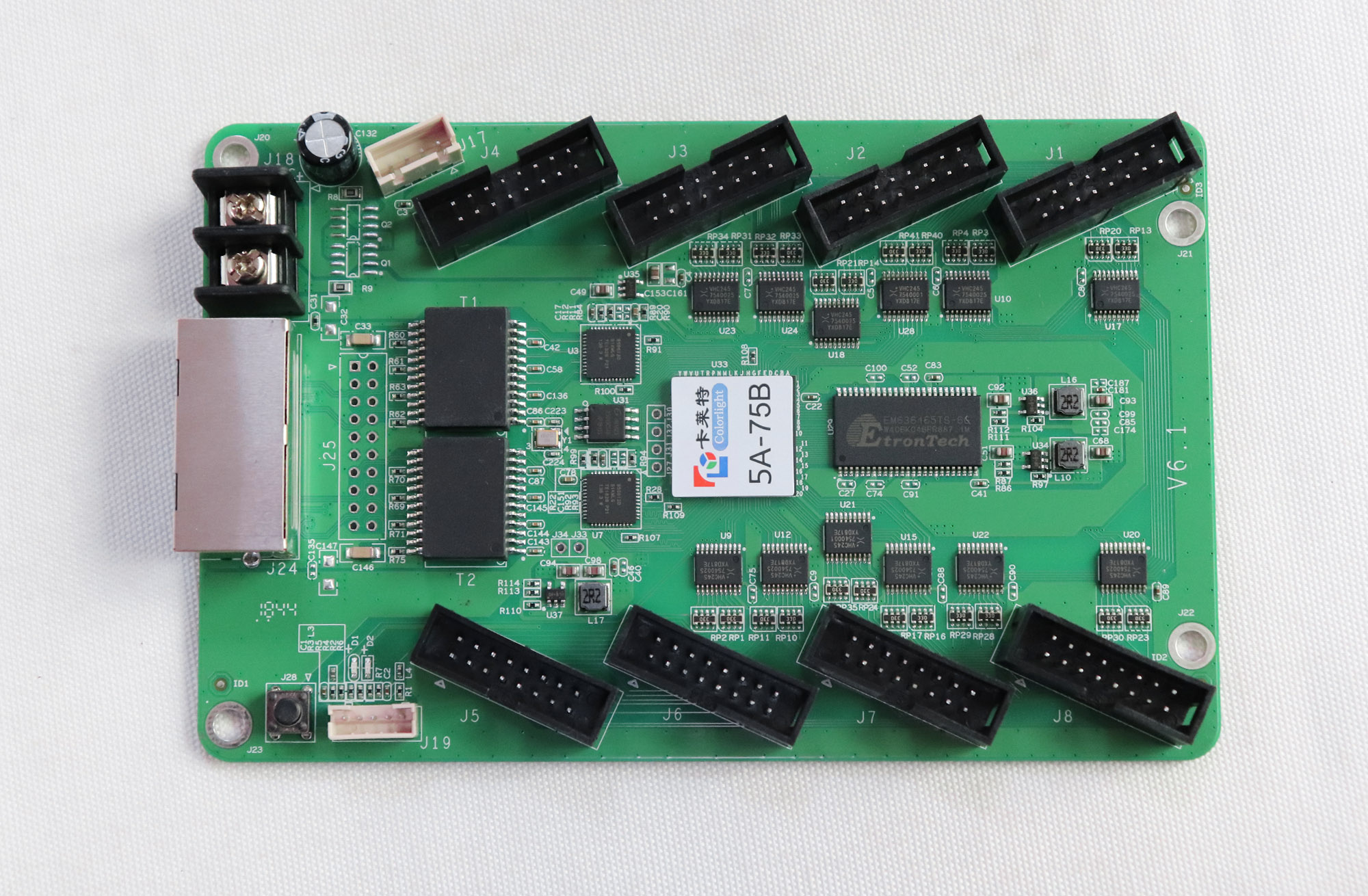
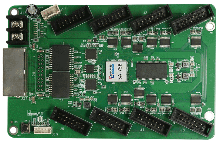
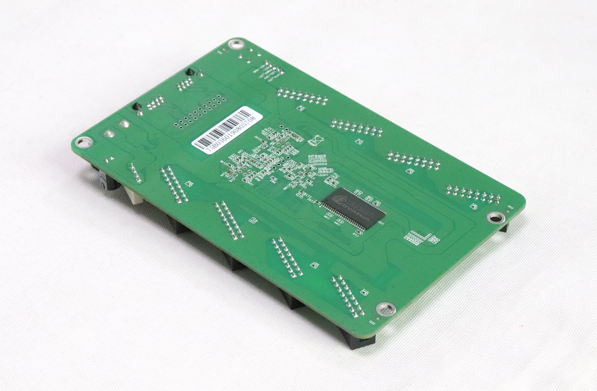
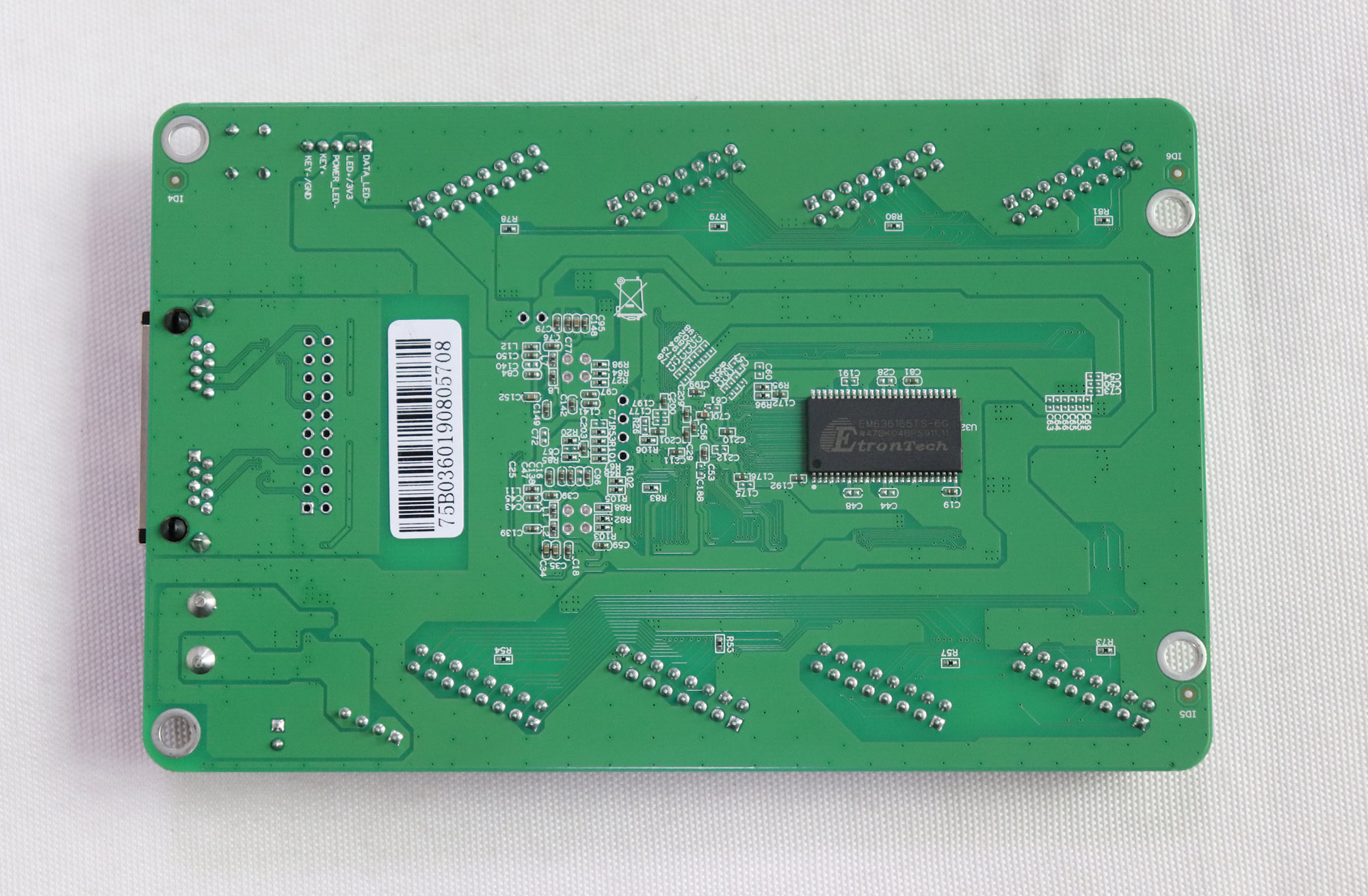
Avoid choosing a receiving card’s load from an isolated maximum-resolution claim. Usable width, height, and performance depend on the exact hardware, firmware, module driver, and intended display settings. Check the matching specification before assigning a cabinet load. The photographs here show particular board revisions; use the markings on your own card when checking electrical connections.
2. Check Power, HUB75 Cables, and the Signal Path
Switch off the relevant equipment before moving power wires or ribbon cables. Verify the receiving card’s permitted DC supply against its revision-specific documentation, then check terminal polarity. Power the LED modules through their specified power connectors; do not treat a HUB75 ribbon cable as the module’s power feed.
Inspect for loose hardware and contact between exposed solder joints and conductive cabinet surfaces. Use suitable standoffs and keep ribbon cables free from sharp bends.
Check each HUB75 cable against the module’s input marking and pinout. Align the connector correctly and confirm that it is fully seated. A matching connector shape does not prove signal compatibility. Follow the module’s documented input-to-output direction when chaining modules.
Trace the display signal from the sending device’s LED output to the first receiving card and onward through the intended chain. Keep that path separate from the computer’s control connection to the sender. An RJ45 socket does not, by itself, indicate an ordinary office-network connection. During initial diagnosis, use a short, known-good cable and one receiving card where practical. Expand the chain only after that section works.
3. Choose the Right Software and Detect the Receiving Card
Check software compatibility before following an older tutorial. Current Colorlight configuration workflows use LEDSetting. Older installations may use LEDVISION’s screen-control tools. Colorlight’s LEDVISION 9.0 release notes document the separation of playback and screen configuration and the removal of network-card mode.
In LEDSetting V2.2.6, start with Device info and select Detect. Connect the computer to the sender through the control interface specified for that sender; the receiver connects through the display-data path. Confirm the detected sender and compare each output’s receiver count with the physical installation.
If detection fails, first inspect power, communication connections, required drivers, and the selected device. If only downstream receivers disappear, inspect the link after the last detected card. Repeatedly changing scan settings will not repair a disconnected signal chain.
Record software and firmware versions so a later Colorlight 5A-75B setup can follow the same workflow.
4. Configure Module Parameters for Your Colorlight 5A-75B Setup
Start with one known cabinet or a controlled test section. In LEDSetting V2.2.6, open Screen config > Screen parameters and use Import to load the matching receiver parameter file. Verify the target selection before sending anything. Apply changes only to the intended receiver while checking the result.
Normal mode supports importing, reading back, sending, and saving parameters. Expert mode permits editing. Use the supplier’s verified file whenever available, especially with unfamiliar driver chips or unusual module routing. Do not overwrite every cabinet simply because a file opens successfully.
When a suitable file is unavailable, Intelligent settings can guide module configuration if the receiver firmware supports it. Identify the driver and decoder ICs, module type, data groups, and the output group used for testing. Respond to each displayed pattern according to what the module actually shows. Guessing through polarity or pixel-routing prompts can produce a partly recognizable but incorrect image.
Check red, green, blue, white, and black patterns at a suitable brightness. Inspect row order, missing pixels, repeated areas, and grayscale transitions. A correct white image alone cannot confirm channel order. Verify the complete area driven by the card, including modules beyond the first output.
Begin performance tuning with validated settings. If a change introduces artifacts, restore the last working values. A stable Colorlight 5A-75B setup should display correct geometry and colors before advanced timing adjustments.
5. Map Cabinets and Verify the Display Order
Module parameters describe how a receiver drives its connected LEDs. Screen mapping assigns that receiver’s pixels to a location in the overall image. Correct cabinet test patterns can therefore coexist with a scrambled full-screen picture.
Open Screen config > Screen mapping in LEDSetting. Enter the receiver arrangement and the actual pixel width and height handled by each card. If a cabinet contains multiple receivers, distinguish the cabinet’s total dimensions from each receiver’s portion. Do not enter physical millimeters in pixel fields.
Trace the real cable sequence for each sending port. Follow the screen-view convention shown by the software and label physical cabinets consistently. A route observed from behind the display can appear reversed when compared with a front-view map.
Verify receiver positions using supported identification functions, then display a numbered grid. Check continuity across cabinet boundaries and sending ports. Assign smaller edge sections their actual dimensions. For Colorlight 5A-75B setup, verify each cabinet’s orientation and load individually.
6. Save Settings and Complete the Acceptance Checklist
Sending parameters, saving them to hardware, and exporting a local backup serve different purposes. After the image is correct, use the relevant Save controls for receiver parameters and screen mapping. In LEDSetting V2.2.6, the screen-parameter Save operation stores parameters in the receivers. Follow the software’s confirmation messages and verify the selected targets.
Complete the Colorlight 5A-75B setup with these checks:
- Every expected receiver is detected on the correct sending port.
- Color patterns, grayscale, and the full-screen grid appear correctly.
- Normal content fills the intended area without repeated or missing sections.
- A controlled power cycle restores the saved configuration with the normal source reconnected.
- Backups identify the cabinet type, software version, firmware, and date.
Keep the final files with the physical connection record. After restarting, inspect the actual screen rather than relying only on a successful-save message. Confirm any project-specific brightness or calibration settings separately.
7. Troubleshoot Common Setup Problems
When Colorlight 5A-75B setup produces an unexpected result, identify whether the fault affects one module, one receiver, or the entire chain. Change one variable at a time and preserve the last working configuration. Use the table to choose the first check, rather than treating every symptom as a firmware problem.
| Symptom | First check | Next action |
|---|---|---|
| Whole screen black | Power, detection, source signal | Restore the missing link first |
| Wrong colors | RGB order and module parameters | Verify separate color patterns |
| Repeated image | Receiver size and screen map | Correct dimensions and positions |
| Missing section | Ribbon cable and output assignment | Check the first affected module |
| Fails after restart | Hardware save and startup source | Read back settings and verify source |
For intermittent faults, note whether the symptom follows a cable, module, or receiving card during a controlled substitution. Switch off before moving module wiring. If the fault remains unexplained, provide the supplier with board photographs, chip markings, versions, and the smallest configuration that reproduces it.
8. Colorlight 5A-75B Setup FAQ
Can I connect a Colorlight 5A-75B directly to a PC without a sending controller?
Some legacy workflows use a compatible Gigabit network adapter and an older LEDVISION version with network-card mode. This is a version-dependent arrangement, not a capability to assume in current software. LEDVISION 9.0 removed that mode. Confirm the exact software, adapter, and receiving-card support before choosing direct connection. A supported sending controller is the straightforward route for the LEDSetting workflow described here. Connecting the card to a router does not substitute for a display-data source.
Can I copy a configuration file from another cabinet during Colorlight 5A-75B setup?
Only after confirming that the donor cabinet matches the module electronics, scan arrangement, wiring, receiver revision, and pixel layout. Similar cabinet size or the same pixel pitch is insufficient. Also identify what the file contains: receiver parameters are different from the whole-screen connection map. Preserve the recipient’s backup and validate one cabinet first. Pixel calibration data belongs to the measured LEDs and should not be copied indiscriminately from another cabinet, even when its receiver parameters are suitable.
Do I need to update the receiving card firmware before setup?
Not automatically. First establish whether the installed firmware supports the intended modules and software functions. Update when a verified compatibility requirement or relevant fix calls for it, using a package approved for the exact card revision and driver category. Back up the working settings and arrange stable power and communication before starting. A newer version number alone is not enough reason to change a functioning installation, and firmware cannot correct reversed ribbon cables or an incorrect map.
Can a replacement 5A-75B use the old card’s settings?
Often, provided the replacement revision and firmware support the existing cabinet configuration. Verify compatibility before installing it, then restore the correct receiver parameters and check its position in the signal chain. Keep calibration recovery separate from parameter recovery; replacing a card does not justify borrowing another cabinet’s calibration values. If the failed card cannot be read, request the original commissioning files or a verified configuration for that exact cabinet from its supplier.
Why can two LED modules with the same pixel pitch require different settings?
Pixel pitch specifies LED spacing. It does not define the driver IC, decoder, scan ratio, internal routing, signal polarity, or connector assignment. Manufacturers can build modules with identical pitch and dimensions but different electronics. Check the PCB markings and obtain the module specification rather than choosing a preset solely by a label such as P3 or P5. Even a visually similar replacement should be verified before being added to an existing cabinet.
Can I use a 5A-75E configuration file on a 5A-75B?
Do not assume direct interchangeability. Related model names do not guarantee identical output resources, loading arrangements, firmware support, or parameter behavior. Ask the cabinet supplier for a 5A-75B file matching the actual modules, or have the configuration adapted and validated on one receiver. A file that imports successfully still needs full output, color, and restart checks before wider deployment.
9. Conclusion
Successful Colorlight 5A-75B setup depends on matching the receiving card to the actual module electronics and cable layout. Verify power and connections first, detect the complete chain, establish correct module parameters, and then map every receiver to its screen position. Save the validated configuration to hardware and keep an identifiable backup.
The completion test is a correctly mapped, stable image that returns after a controlled restart. Use each fault’s location and symptoms to choose the next check, preserving the working configuration for future maintenance.