Quick answer: An LED display driver IC receives image data from the receiving card or video processor, converts it into PWM timing and regulated output current, and drives each LED channel. Its current accuracy, grayscale capability, refresh rate, diagnostics and power efficiency directly affect brightness uniformity, camera performance, viewing comfort and the service life of an LED screen.
This guide explains the function of an LED display driver IC, the specifications that matter in real installations, and the current trends shaping indoor, outdoor and fine-pitch LED displays. For component-level background, compare your design with the LED driver fundamentals published by Texas Instruments.
What is an LED display driver IC?
An LED display driver IC is the electronic interface between the display controller and the LEDs on an LED module. It receives serialized RGB data according to the selected protocol, stores or shifts that data through its channels, and controls the timing and current used to light each pixel. In a typical synchronous LED display, the driver IC works with the receiving card, row-scan circuit and power supply to turn digital image data into visible light.
LEDs are current-driven devices: after an LED reaches its forward-voltage range, brightness is primarily determined by current. For that reason, a dedicated driver IC normally uses a constant-current output instead of relying on a simple voltage drive. Constant-current regulation helps keep red, green and blue channels consistent, reduces brightness variation between modules and prevents visible flicker caused by unstable drive conditions.
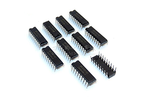
Driver ICs can be grouped into general-purpose logic devices and dedicated LED driver ICs. General-purpose devices may provide shift-register or logic functions, while dedicated devices combine those functions with constant-current sinks and LED-specific features such as PWM control, output-enable timing, error detection, current gain adjustment and per-channel correction.
How an LED driver IC works
- Data reception: The IC receives pixel data and clock/latch signals from the receiving card or controller.
- Data storage and shifting: Internal registers align the data with the correct RGB channels and scan rows.
- PWM processing: PWM timing converts grayscale values into controlled on-time for each LED channel.
- Constant-current output: Regulated sink current drives the LEDs with repeatable brightness across the module.
- Refresh and output control: OE, latch and scan timing determine when data is displayed and prevent ghosting during transitions.
The result is not just a brighter screen. The driver IC determines whether the display looks smooth at low brightness, remains readable on camera, reproduces gradients without banding and maintains uniform color across a large cabinet.
Key performance specifications
Refresh rate and camera performance
Refresh rate is the number of complete image updates per second. A higher refresh rate, combined with correct scan timing and a fast communication interface, reduces rolling lines and black bands when an LED screen is filmed. For broadcast, live events and virtual production, evaluate the complete signal chain—not only the headline refresh-rate number—including receiving-card settings, scan mode, shutter-speed tests and PWM architecture.
Grayscale and low-brightness quality
Grayscale resolution determines how smoothly the display renders gradients, shadows and skin tones. High grayscale at low brightness is especially important indoors, where viewers sit close to the screen and eye comfort matters. Ask for a low-brightness test pattern and check for color shifts, contouring and uneven gray levels before approving a driver IC.
Constant-current accuracy and channel matching
Current matching between output channels affects white balance and color uniformity. A driver IC with stable constant-current regulation helps prevent bright and dark pixels, color blocks and module-to-module differences. Review the specified current range, channel-to-channel matching, thermal behavior and the calibration method used by the display manufacturer.
PWM, ghosting and scan control
Advanced PWM and carefully controlled OE/latch timing reduce ghosting, streaks and edge artifacts, particularly on high-scan-rate modules. The driver should be compatible with the module’s scan ratio and the receiving card’s timing requirements.
Thermal performance and power efficiency
Power is lost as heat in both the LEDs and the driver IC. Lower constant-current dropout voltage and efficient internal logic can reduce heat generation without sacrificing image quality. Some modern devices support a low dropout voltage around 0.2 V and can operate with a lower supply headroom than traditional designs; confirm the value in the manufacturer’s datasheet and test it in the finished cabinet.
Why driver IC integration matters for fine-pitch LED
As pixel pitch decreases, more pixels and more driver channels must fit on each module. A conventional P1.9 small-pitch LED module, for example, can require a high density of constant-current channels and scan components. Crowded routing increases PCB complexity, soldering risk and thermal density.
Higher-channel-count devices—such as 48-channel constant-current driver ICs—integrate peripheral logic and reduce the number of packages on the PCB. This can free routing space, improve assembly reliability and support thinner fine-pitch modules. The right choice still depends on scan ratio, package layout, output current, heat dissipation and compatibility with the control system. See our P1.9 small-pitch LED cabinet example for an application context.
Driver IC evolution and current trends
LED display driver technology has progressed from basic shift-register control to highly integrated constant-current devices with sophisticated PWM and diagnostics. Early generations supported modest grayscale levels; later generations increased channel density, communication speed and image-processing precision. Today’s designs focus on three practical goals:
- Energy efficiency: reduce dropout voltage, operating current and heat while maintaining stable brightness.
- Integration: combine more channels and logic in one package to simplify fine-pitch PCB layouts.
- Image quality: improve low-gray performance, refresh rate, current matching, ghost suppression and calibration support.
How to choose the right LED display driver IC
- Define the application: indoor, outdoor, rental, fixed installation, broadcast or close-viewing signage.
- Match the scan architecture: confirm scan ratio, row-driver arrangement, output current and module wiring.
- Set image requirements: specify minimum refresh rate, grayscale at low brightness and camera-shooting requirements.
- Check electrical margins: review supply voltage, dropout voltage, maximum channel current and thermal limits.
- Verify compatibility: confirm protocol, receiving card, firmware, OE/latch timing and PCB footprint.
- Test a complete module: inspect white balance, gray ramps, motion, ghosting, temperature and power consumption—not just the IC datasheet.
Frequently asked questions
Does a higher refresh rate always mean better image quality?
No. Refresh rate must work with PWM frequency, scan timing, receiving-card configuration and the camera shutter speed. A balanced system delivers better results than a single high specification.
Why does an LED display flicker at low brightness?
Possible causes include insufficient PWM resolution, unstable constant-current regulation, incorrect OE timing, low refresh settings or a mismatch between the driver IC and receiving card. Test the module at several brightness levels and check the complete signal chain.
What is the benefit of constant-current output?
It keeps LED current more consistent than a simple voltage drive, improving brightness and color uniformity and reducing visible variation between pixels and modules.
Can one driver IC be used for every LED module?
No. Driver IC selection depends on scan ratio, channel count, current, package, protocol, PCB design, refresh target and the receiving-card ecosystem. Always validate the exact module and controller combination.
Conclusion
The LED display driver IC is a core component that determines how accurately an LED screen converts digital data into light. Constant-current control, PWM grayscale, refresh performance, current matching, thermal efficiency and integration all influence the final viewing experience. Selecting the IC together with the module, receiving card and cabinet design helps deliver a stable, uniform and camera-friendly LED display.