An LED processor prepares the video image; an LED controller sends and maps that image to the LED screen. A processor handles tasks such as scaling and source switching. A controller works with compatible receiving cards to deliver the right pixels to the right cabinets. An all-in-one unit can combine both functions, so you do not always need two separate boxes.
This guide explains LED video processors, LED screen controllers and controller cards for modular LED walls. It does not cover the small dimmers used with LED light strips.
LED processor vs LED controller: key differences
The distinction is about function, not the product name. Vendors may call a combined processor and sender an LED video controller, LED wall processor or all-in-one controller. Check the actual inputs, processing features and LED output ports.
| Feature | LED processor | LED controller |
|---|---|---|
| Main job | Prepare the image for the display canvas. | Map and distribute image data to LED cabinets. |
| Typical functions | Scaling, cropping, source switching and layers; advanced functions vary by model. | Screen mapping, output loading and brightness control, with supported calibration and monitoring. |
| Signal connections | Video inputs such as HDMI, DVI, SDI or DisplayPort, depending on the model. | Video input or an integrated processing path; dedicated LED data outputs to compatible receiving cards. |
| What to check | Input resolution, frame rate, layers, scaling quality, HDCP and latency. | Total pixels, per-port limits, canvas dimensions, receiving-card compatibility and backup modes. |
| When needed | When the source or upstream equipment cannot provide the required image size, layout or switching. | A compatible control system is needed to drive a modular LED wall. |
| Can one device do both? | Yes. An all-in-one controller includes video processing. | Yes. Verify both processing and sending capabilities before buying. |
What does an LED video processor do?
An LED video processor receives a video signal and adapts it to the LED wall’s pixel canvas. This matters when a screen has a non-standard aspect ratio or a different resolution from the source.
- Scale and crop: fit the source to the wall, preserve its aspect ratio or crop selected areas.
- Switch sources: select a laptop, camera or media player. Seamless switching depends on the model and input formats.
- Arrange layers: show picture-in-picture or multiple windows when supported.
- Manage signal compatibility: configure input timing and EDID; confirm the required HDCP version throughout the signal path.
- Adjust image appearance: apply supported colour, contrast and gamma controls. HDR, 3D LUTs, genlock and frame-rate conversion are model-specific features.
For example, a 1920 × 1080 laptop image sent to a 1536 × 768 LED wall needs a deliberate scaling or cropping choice. Stretching it to fill the canvas changes the aspect ratio. A processor—or a controller with a built-in scaler—lets you choose how to present it.

What does an LED controller do?
An LED display controller, also called an LED screen controller or LED panel controller, manages how image data reaches a modular display. The term may refer to a sender box, a sending card, a media-player controller or the wider control system.
Sending card or sender box
The sending stage assigns areas of the image to output ports and transmits LED data to the screen. Its capacity, maximum canvas width and height, and port configuration limit the display it can load. A video input alone does not prove that the sender can scale an image.
Receiving cards inside the screen
Receiving cards decode data for their assigned modules and pass control signals through hub connections to the module driver ICs. They work with the panel hardware and configuration to produce the displayed image. Calibration, monitoring and backup functions depend on the supported combination.
Use a compatible sender, receiving-card family, firmware and panel configuration. A shared RJ45 connector does not establish compatibility between brands. Dedicated LED data outputs should not be treated as ordinary LAN ports unless the manufacturer explicitly supports that network topology.
Synchronous, asynchronous and all-in-one controllers
- Synchronous controller: displays a live input from a computer, processor or another video source.
- Asynchronous media-player controller: plays stored or scheduled content for signage. Some models also support live input or dual-mode operation.
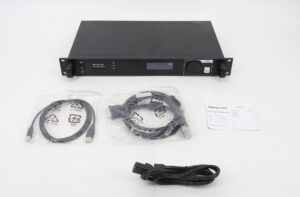
- All-in-one processor/controller: combines scaling and other supported video functions with LED sending outputs.
How the LED display signal chain works
Typical separate-device setup:
Video source → video processor → sending controller → receiving cards → hub connections and driver ICs → LED modules.
Typical all-in-one setup:
Video source → all-in-one processor/controller → receiving cards → LED modules.
The processor prepares the canvas. The sending stage divides it among output connections. Receiving cards deliver the assigned image regions to the modules. An asynchronous player adds stored-content playback before the sending stage.
Do you need both a processor and a controller?
You need both functions when the source requires processing, but those functions can be in one device. Select a separate processor when the integrated features do not meet your input, layout, switching or production requirements.
| Application | Possible setup | Verify before purchase |
|---|---|---|
| Single-source presentation | Source plus an all-in-one controller, or a sender if the source already matches the canvas. | Scaling, supported timing and total pixel load. |
| Scheduled signage | Asynchronous media-player controller plus compatible receiving cards. | Playback formats, scheduling, storage and remote access. |
| Live event with several sources | All-in-one unit with sufficient inputs and layers, or a separate processor and sender. | Switching behaviour, layer limits, latency and backup operation. |
| Broadcast or virtual production | A processing and control system specified for the complete camera workflow. | Genlock, shutter interaction, colour pipeline and measured end-to-end delay. |
NovaStar example: the VX1000 integrates video processing and video control. NovaStar specifies 10 Ethernet outputs and a total loading capacity of 6.5 million pixels. This is a concrete example of why “processor” and “controller” do not necessarily mean separate boxes. See the official VX1000 specifications; do not transfer its limits to other models.
How to calculate LED controller pixel capacity
Start with the screen’s actual pixel resolution, not its physical size or the source video resolution.
- Total pixels = screen width in pixels × screen height in pixels.
- Check the sender’s total load and maximum canvas width and height.
- Use the exact per-port loading limit for the required input frame rate and bit depth.
- Map complete cabinets to ports and verify receiving-card limits and cable routing.
- Plan backup outputs separately from the ports carrying the normal display load.
The following calculation uses 650,000 pixels per output as an illustrative assumption, not a universal Ethernet standard. Minimum ports = round up(total pixels ÷ allowed pixels per port). Real layouts can require more ports because of cabinet geometry or other device limits.
| Screen resolution | Total pixels | Arithmetic minimum |
|---|---|---|
| 1920 × 1080 | 2,073,600 | 4 ports |
| 3840 × 2160 | 8,294,400 | 13 ports |
| 7680 × 4320 | 33,177,600 | 52 ports |
These figures do not prove that a particular controller can accept a 4K or 8K input or drive that canvas. Input bandwidth, total capacity, maximum dimensions and system topology must all fit. Higher video frame rates or input bit depths can reduce loading capacity; LED PWM refresh and internal grayscale settings are different parameters and should not be substituted into the bandwidth calculation.
For more detail, read our NovaStar LED controller pixel-load sizing guide.
Refresh rate, camera performance and latency
A 60 Hz video input describes incoming frames per second. An LED refresh specification such as 3840 Hz describes panel drive behaviour; it does not mean the wall receives 3840 distinct video frames per second.
Camera results depend on the LED driver ICs, scan pattern, receiving-card configuration, brightness, camera shutter and synchronisation. A high refresh specification alone does not guarantee a band-free image. Test the complete screen with the intended camera settings, including low brightness and fast shutter speeds.
Likewise, there is no universal one- or two-frame delay for every processor/controller pair. At 60 frames per second, one frame lasts about 16.7 ms, but total source-to-light latency also includes the camera or player, converters, processing and panel drive. Check the documented mode and measure the complete workflow when delay matters.
Troubleshooting: processor, controller or panel?
| Symptom | Possible area | First checks |
|---|---|---|
| Black screen after changing source | Input format, cabling or handshake | Confirm a supported source timing, selected input and end-to-end HDCP compatibility. |
| Stretched or cropped picture | Scaling or canvas configuration | Compare source aspect ratio, processor output canvas and screen mapping. |
| Cabinets show the wrong part of an image | Port map or cabinet order | Check receiving-card mapping and the physical connection order. |
| Rolling bands on camera | Panel drive and camera interaction | Test shutter and frame-rate settings, synchronisation and the supported panel configuration. |
| Colour or brightness differs between cabinets | Calibration or module configuration | Check calibration data, receiving-card settings and replacement-module consistency. |
| Intermittent cabinet dropouts | Signal path, port load or power | Check connections, approved cable lengths, port loading and power stability. |
Change one variable at a time and keep a backup of the working screen configuration. A controller test pattern can help separate a source/processor problem from a downstream screen problem.
Frequently asked questions
What is the difference between an LED processor and an LED controller?
An LED processor adapts the video image through functions such as scaling and switching. An LED controller maps and sends image data to compatible receiving cards. An all-in-one unit combines both roles.
Does an HDMI input mean my LED controller has a scaler?
No. HDMI identifies an input connection, not a processing capability. Check whether the exact controller supports scaling, cropping and the required output canvas.
Is an LED controller card the same as a receiving card?
Not necessarily. “Controller card” can describe a sending card, an asynchronous control card or another control board. A receiving card is the downstream board that supplies data to LED modules. Identify its role and supported control system before ordering.
Can I use an all-in-one controller for multiple sources?
Yes, if it supports the input count, switching behaviour and layers you need. Multiple sources do not automatically require a separate processor.
Can I mix NovaStar, Huidu, Colorlight and Linsn cards?
Do not assume cross-brand compatibility. Verify the exact sending and receiving hardware, firmware and configuration requirements with the manufacturer. Matching connectors are not enough.
How many pixels can an LED controller output port handle?
Use the specified limit for that model and operating mode. Around 650,000 pixels is a common planning example for some Gigabit LED outputs, but it is not a guaranteed limit for every system. Also check the total controller and receiving-card capacities.
Does 3840 Hz refresh guarantee flicker-free camera footage?
No. Camera shutter, panel scanning, brightness and synchronisation also matter. Evaluate the full display and camera combination under the intended shooting conditions.
Choose by function, capacity and compatibility
Match the processor to your video sources and image layout. Match the controller to the pixel canvas, receiving cards and reliability requirements. Choose an all-in-one device when it covers both sets of needs, and separate devices when the project requires capabilities beyond the integrated unit.
When requesting a recommendation, include the screen resolution, cabinet arrangement, receiving-card model, source formats and whether the screen will be filmed. Contact our team with those details to check a suitable configuration.