Short answer: LED controller bench testing means running the whole control system — controller or sending card, receiving cards, hub cards, power supplies, cables and at least one real LED module — on a workbench before anything ships to site. A structured two to four hour session proves the signal chain end to end: the controller boots, the software detects every card, the receiving cards drive the modules with the correct scan and color, and the 5 V rail holds under load. The same faults found on site cost a production day, a crane booking or an air freight of spare parts.
Key takeaways
- Factory QC tests a product. Bench testing verifies your purchase as a system: card to card, card to module, card to power supply.
- Run the test in this order: inventory → visual inspection → power supplies alone → controller boot → data link → receiving-card parameters → test patterns → burn-in → record.
- Never test an LED controller without a real load. One known-good module reveals scan, port and color faults that a bare controller never shows.
- Record firmware versions, parameter files (RCG / RCVBP / RCVP), measured voltages and photos. That record is what resolves a warranty claim later.
- Bench testing cannot prove on-site grounding, cable runs across a building, enclosure temperature or viewing distance — those stay in commissioning.
Table of contents
- Why bench testing beats trusting the packing list
- What “the whole purchase” actually includes
- The 10-step bench test
- Test patterns that reveal real faults
- Bench test vs. on-site commissioning
- Failure modes you catch on the bench
- Tools, software and fixtures to prepare
- How to record the result
- Common mistakes
- FAQ
Why bench testing beats trusting the packing list
A carton that matches the invoice only proves that the boxes arrived. It says nothing about whether a NovaStar controller, a set of Colorlight receiving cards and a batch of 5 V power supplies will work as one system on a wall 9,000 km away.
LED display control hardware is modular, and the failure that stops a site is almost never “the controller is dead”. It is a mismatch: a receiving card from a different batch running an older firmware, a hub adapter with the wrong pinout for the module’s scan mode, a 5 V supply that sags at full white, or an RCG parameter file written for 1/8 scan loaded onto 1/16 scan modules. Each of those parts passes its own factory test and fails as a system.
The economics are simple. On a bench you can swap one variable at a time — cable, card, module, supply — in minutes. On site, the same swap means climbing a truss, isolating a cabinet and re-running cable. Because the site is usually a fixed date with a client watching, bench testing is less about quality control and more about risk transfer: you move the debugging into a room where failure is cheap.
For a wider view of how the pieces fit together, see our guide to the LED display controller signal flow and sizing.
What “the whole purchase” actually includes
Bench testing a controller in isolation is the most common mistake in this workflow. Test the purchase as a chain, because that is how it will be installed.
| Item | Role in the system | What to verify on the bench |
|---|---|---|
| Sending card / sender box / video controller | Converts the video source into a Gigabit data stream for the screen | Boots from cold, is detected by the software, reports firmware version, every data output lights and carries signal |
| Video processor (optional) | Scaling, switching and multi-window on larger systems | Output resolution and port mapping match the screen design; no unexpected scaling or frame-rate conversion |
| Receiving cards | Receive the stream and drive the module rows | Status LEDs behave as documented, card is detected, scan and parameter set are correct, dead-pixel status readable |
| Hub card / adapter board | Splits the receiving card output into HUB75 / HUB75E ribbon ports | Port count and pinout match the modules, ribbon connectors seat with no bent pins, every port drives a real module |
| Power supplies | Typically a regulated 5 V DC rail for modules and logic | Output voltage at no load and under load, terminal torque, heat after continuous operation |
| Data and power cables | CAT5e / CAT6 for controller-to-card, ribbon for card-to-module | Continuity, correct crimp, correct length, link stability when the cable is flexed |
| Sample LED modules or cabinet | The real load and the real scan mode | Scan match, dead pixels, color, brightness consistency across the sample |
| Software, firmware and parameter files | Configuration and acceptance files | Version installed, license valid, RCG / RCVBP / RCVP files match the modules, files backed up |
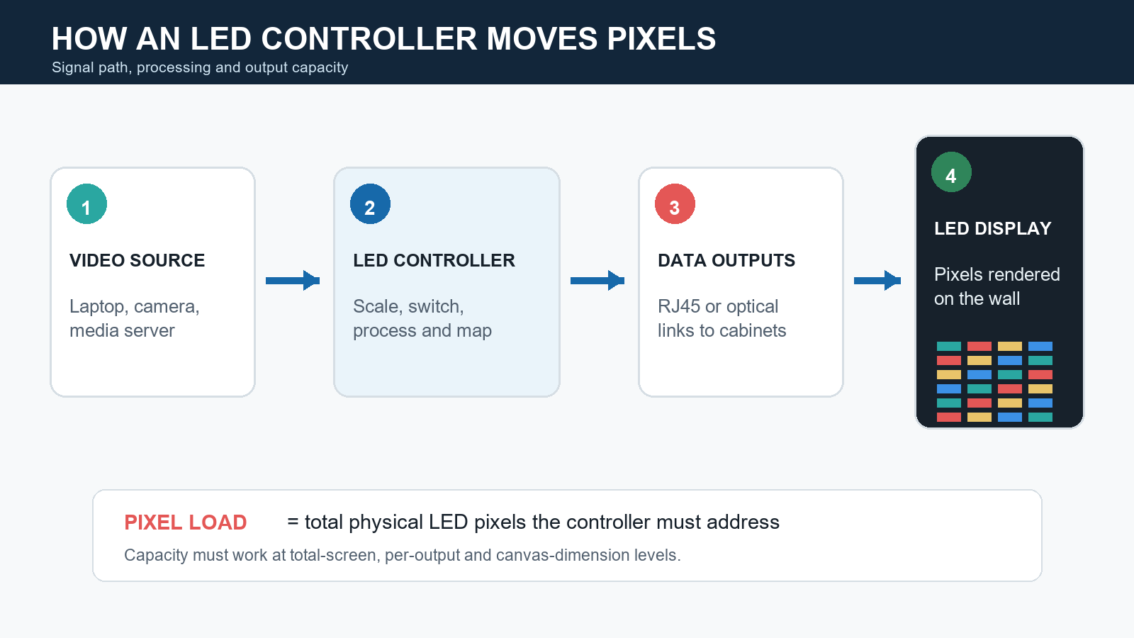
Bench testing follows the same path the signal takes on site: source → controller → Ethernet data → receiving card → hub → module.
The 10-step LED controller bench test
1. Inventory against the packing list
Count cards, adapters, power supplies and cables; write down model numbers and serial numbers before anything is powered. Photograph the cartons as opened. This step is boring and it is the one that catches a short shipment while the supplier can still fix it quickly.
2. Inspect before power
Look for bent ribbon pins, cracked connectors, loose electrolytic capacitors, solder splashes, missing thermal pads and screws rattling inside a sender box. Check that the module ribbon sockets are not pushed in. Anything damaged here is a straight replacement request, not a test result.
3. Verify the power supplies on their own
Measure each supply with a multimeter before connecting cards: output voltage at no load, then again with a representative LED load attached. Watch the measured value for a minute or two — a rail that starts at 5.05 V and drifts down under load will cause random resets later. Confirm terminal screws are tight and that the mains side is properly shrouded.
4. Boot the controller and confirm software detection
Connect the controller to the laptop, open the vendor configuration software, and confirm the device appears with the expected model and firmware version. Use the matching toolchain: NovaLCT or SmartLCT for NovaStar, LEDVISION or iSet for Colorlight, LEDStudio for Linsn, and the HDPlayer / HDSet family for Huidu. Download hubs for these are listed in our NovaStar software download, Colorlight software download and Linsn LEDStudio download pages.
A controller that boots but is invisible to the software is normally an IP, driver or adapter problem, not a dead unit — resolve it now rather than on site.
5. Prove the controller-to-receiving-card data link
Connect one receiving card with a short, known-good CAT5e/CAT6 patch cable and confirm the card is detected in the software. Then repeat with the exact cable length and type you plan to install. Gigabit Ethernet over copper is specified for 100 m per segment, and cheap or badly crimped cable fails well before that, especially in a hot cabinet.
6. Load the receiving-card parameters
Load the correct configuration file for the module’s scan mode and resolution (RCG for Linsn, RCVBP / RCVP for Colorlight, the equivalent parameter file for other brands) and then read it back from the card. Save a copy of the file with the order number. This is the single step that most often explains a “half-cabinet” or “scrambled image” complaint on site.
7. Drive real modules with test patterns
Connect at least one known-good module through the hub card and run test patterns. Confirm scan mode, orientation and color order. If the image is mirrored, flipped or color-swapped, fix it in software and record the setting rather than physically reversing the module on site.
8. Check port mapping and hub configuration
Move the module from port to port and confirm each HUB75 / HUB75E port works. On multi-output controllers, verify that output 1 maps to the cabinet position your drawing expects. On site this is a logic problem people usually misdiagnose as faulty hardware; on the bench it takes ten minutes.
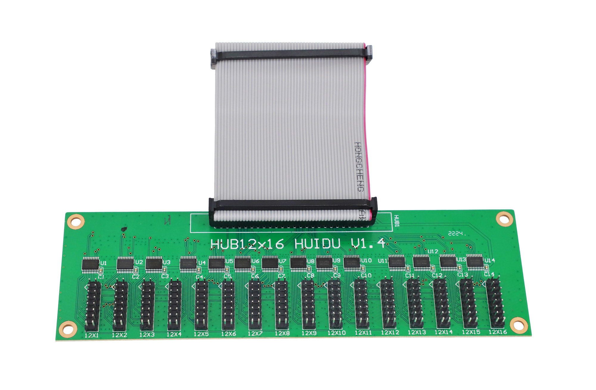
Test every hub port, not just the first one. A single faulty ribbon socket is enough to take out one cabinet on site.
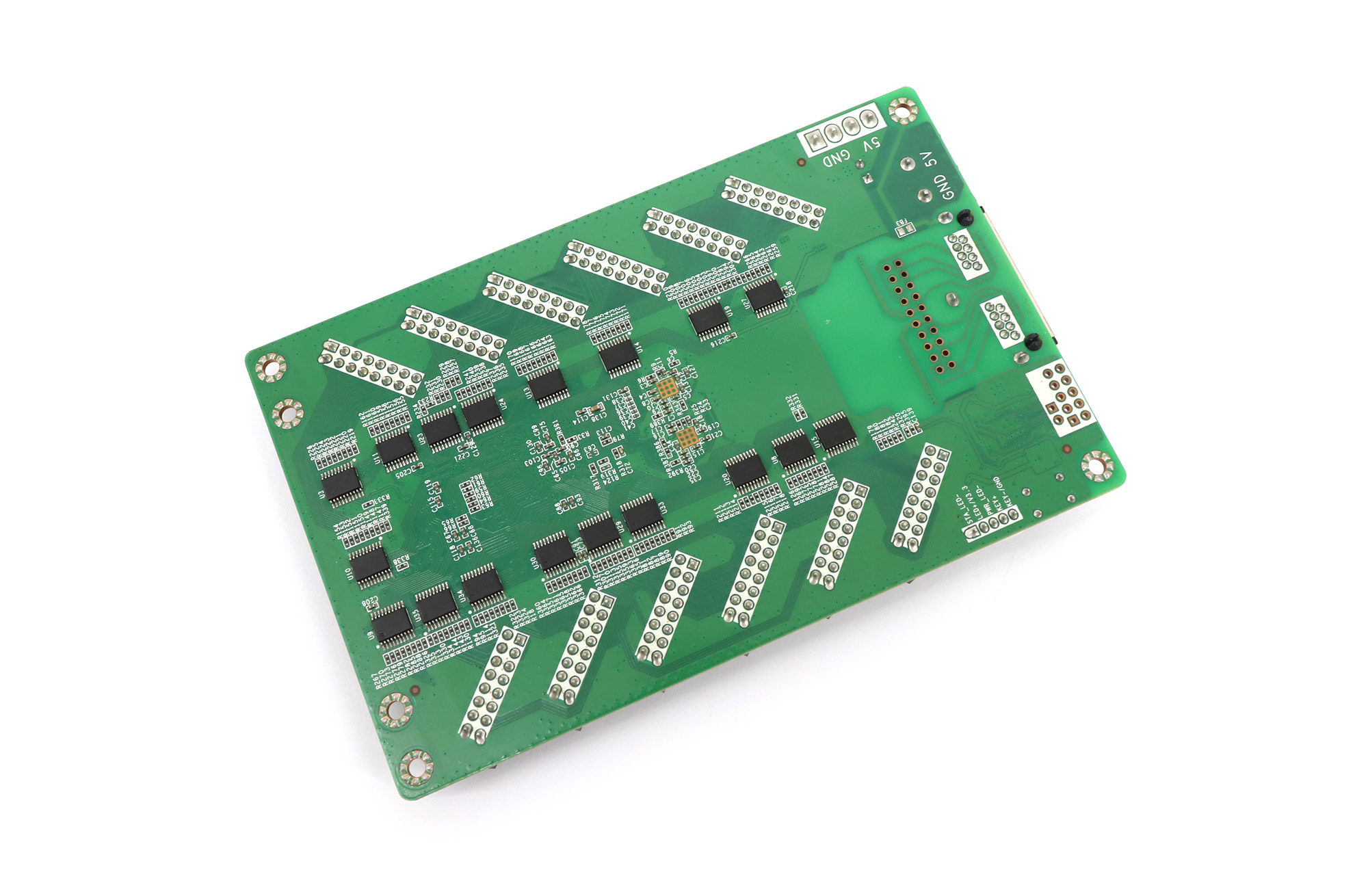
A receiving card with multiple HUB75E ports is the fastest way to test port mapping and scan configuration before installation.
9. Run a burn-in while watching temperature
Leave the system running a full-white and moving-content pattern for several hours so the boards reach thermal steady state. Watch for a card that becomes noticeably hotter than its neighbours, a power supply that gets too warm to touch safely, or a display that dims and resets after twenty minutes. Combining a bench burn-in with the manufacturer’s own aging report gives the best coverage of early-life failures.
10. Freeze the configuration and record the evidence
Export the parameter files, note firmware versions, photograph the working test setup, and store everything with the order documentation. When the same system is commissioned six months later by a different technician, this package is what makes the difference between a five-minute fix and an argument.
Test patterns that reveal real faults
| Pattern | What it reveals |
|---|---|
| Solid red, then green, then blue | Dead or stuck pixels in a single color channel; driver channel faults that look fine on white |
| Full white | Power headroom, brightness uniformity, connector and ribbon heating |
| Grayscale steps and low-brightness content | Banding, poor low-gray performance, driver IC or scan issues |
| Gradient / color ramp | Color temperature drift across cabinets and bit-depth limits |
| Scan test or single-pixel lines | Row-select faults, wrong scan mode, ribbon seating, HUB port faults |
| Moving text and video | Refresh behavior, tearing, frame synchronization between outputs |
Bench test vs. on-site commissioning
Bench testing and commissioning answer different questions. Trying to do one on the other’s territory is how projects lose days.
| Question | Bench | Site |
|---|---|---|
| Does every card work and match its parameter file? | Yes — this is the core purpose | Too late; you are debugging under time pressure |
| Is the firmware consistent across the shipment? | Yes | Hard to check once cabinets are closed |
| Does the power rail hold at full white? | Yes, with a representative load | Confirm again with the real cabinet load |
| Grounding, earthing and mains quality | No | Yes |
| Cable runs across the building | Only the sample length you test | Yes |
| Enclosure temperature and airflow | No | Yes |
| Brightness and uniformity at viewing distance | No | Yes |
Failure modes you catch on the bench
- Dead or intermittent receiving card. Shows as one dark cabinet or a dark half. On the bench it is a two-minute card swap.
- Firmware mismatch inside one shipment. The controller configures normally, but modules show the wrong scan or flicker. Caught by reading back versions per card.
- Wrong hub adapter or pinout. Produces a scrambled or shifted image that looks like a software bug.
- Undersized or drifting power supply. The display is fine on a test image and dims or resets on full white after twenty minutes.
- Bad cable crimp. The link works when the cable is straight and fails when the cabinet is closed and the cable is bent.
- Wrong parameter file for the module scan. Half image, doubled image or inverted rows — the classic site-day emergency.
- Port mapping mismatch. Everything works except the cabinets appear in the wrong order.
Most of these have one thing in common: on site you cannot tell which of them you have, because everything happens at once. On the bench you change one variable at a time.
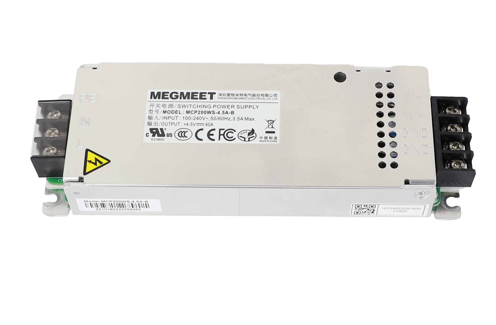
Measure the 5 V rail at no load and again with modules attached. A supply that only looks healthy without load is a common cause of resets at full white.
Tools, software and fixtures to prepare
| Item | Why you need it on the bench |
|---|---|
| Multimeter | No-load and under-load voltage, continuity and polarity checks |
| Bench power supply or the actual shipped 5 V supply | Test with the supply that will be installed; a laboratory supply can hide inrush and sag problems |
| One known-good LED module or small cabinet | Provides the real load, scan mode and pixel layout |
| HUB75 / HUB75E ribbon cables | Card-to-module connection and fault isolation |
| Short patch cable plus a cable of installed length | Separates “the card is faulty” from “the cable is faulty” |
| Laptop with the correct configuration software | Detection, parameter loading, pattern testing |
| Vendor parameter files (RCG / RCVBP / RCVP and equivalents) | Correct scan and resolution for the modules |
| Phone or camera and a test record sheet | Evidence for the supplier and for future maintenance |
| ESD strap and insulated tools | Cards are static-sensitive; a damaged card may pass the bench and fail in the field |
If you are building the system from scratch or adding redundancy, our NovaStar controller selection and pixel-load sizing guide covers capacity maths and spare-part planning, and the controller signal flow guide explains how a processor, controller and receiving card share the work.
How to record the result
An acceptance record that actually protects a purchase contains:
- Order or case reference, test date, technician, ambient temperature
- Model and serial numbers of every controller, sending card, receiving card, hub card and power supply
- Firmware version per card, and the software version used
- Parameter file name for each module type, plus a saved copy
- Measured 5 V values at no load and under load, per supply
- Test patterns run and observed result
- Burn-in duration and any anomaly seen during it
- Defects found, action taken (replaced, passed with note, returned), and photos
Keep this file with the controller configuration. Sites change technicians, and a documented baseline turns “the display is behaving strangely” into a five-minute diagnosis.
Common mistakes
- Testing the controller alone and calling the shipment verified. Without a load, half the failure modes stay invisible.
- Testing every card in the same batch and assuming the rest match. Sample across batches, especially on large orders.
- Using a laboratory supply that cannot deliver real inrush current. It flatters the design and hides supply problems.
- Five minutes at room temperature. Thermal and intermittent faults need time and a full-white load to appear.
- Mixing receiving cards from different firmware versions in one cabinet without recording which is which. When one cabinet misbehaves, that mixing is usually why.
- Not backing up the parameter file. Rebuilding an RCG or configuration from scratch on site is avoidable work.
- No photographs and no record. Without evidence, a warranty discussion becomes a conversation about trust.
For the on-site half of the job, see inspection standards for LED display manufacturers, five power problems that silently damage LED displays and daily operation and maintenance precautions.
FAQ
Can you bench test an LED controller without LED modules?
Only partly. A bare controller can be powered, detected by the software and checked for output link lights, but scan mode, port mapping, color order, brightness and power headroom all require a real module or cabinet as the load. A known-good sample module is the cheapest piece of test equipment in this workflow.
How long should a bench test run?
Long enough for the boards to reach thermal steady state and for intermittent faults to appear — in practice a few hours of continuous operation with full-white and moving content, on top of the manufacturer’s own aging report. For critical installations, extending the run and repeating it after transport is a reasonable safeguard.
Which software do I need to test a controller?
It depends on the brand. NovaStar systems use NovaLCT or SmartLCT, Colorlight systems use LEDVISION or iSet, Linsn systems use LEDStudio, and Huidu systems use the HDPlayer / HDSet family. Always test with the vendor’s own tool: third-party utilities may detect a device but will not load the correct parameter files. Configuration walkthroughs are also published on the EagerLED YouTube channel.
What if the system passes on the bench but fails on site?
The most common causes are mains and grounding quality, cable runs longer or thinner than the sample you tested, enclosure temperature higher than the bench, and parameter files that were changed during installation. Re-test the suspect card with the shortest known-good cable first — that single step separates a hardware fault from an installation fault.
Do spare parts need bench testing too?
Yes. Spares are used in the worst circumstances, often months later, by whoever is on site. Test them the same way as the main order, label them, and keep their parameter files with the rest of the configuration.
Does bench testing affect the warranty?
It depends on the supplier’s terms, but a documented bench test almost always helps. A supplier can act on a fault that is described with model numbers, firmware versions, measured voltages and photographs; without that record, a claim is hard to verify for either side.
Buying a control system that arrives matched
The easiest way to make bench testing quick is to buy hardware that is already matched: controllers, sending cards, receiving cards, hub cards and power supplies from the same brand family, with parameter files for your modules included.
Start with our LED video controllers and sending cards, check the accessory range in control card accessories, and read what to look for in a video receiving card before you order. If you are not sure which combination matches your screen, send us the module model, cabinet size and pixel layout, and we will confirm the controller, card and power supply list before shipping.
Related reading: what an LED processor and an LED controller do, how to install a sending card into an external sender box, and why the power supply deserves its own specification.