Choose an LED screen fiber converter by counting the cabinet feeds you need at the screen, then matching the optical output and the installed fiber. The NovaStar CVT10 can deliver eight or ten Gigabit Ethernet feeds from fiber, depending on the upstream optical encoding. The CVT4K provides two groups of eight and assigns a backup optical port to each group. For either family, order the S version for compatible single-mode fiber or the M version for compatible multimode fiber.
For an AV integrator pricing a fixed video wall, the model decision affects more than the converter line on the quote. It determines how many optical links the rack needs, whether it can use the venue’s existing strands, and which parts the crew needs on site. Use the comparison and example orders below to turn a cabinet map and a route survey into a bill of materials.
1. Count cabinet feeds before selecting an LED screen fiber converter
Start with the approved cabinet map or a preliminary design from the LED system engineer. Count the separate Gigabit Ethernet feeds that must leave the screen-side rack. A feed may drive several cabinets in a chain. The count depends on the controller and receiver combination, cabinet pixel load, required bit depth and frame rate where applicable, and the cabinet manufacturer’s limits for each chain. Have the controller design checked separately from the fiber conversion hardware.
01. Read the optical mode for the port in use
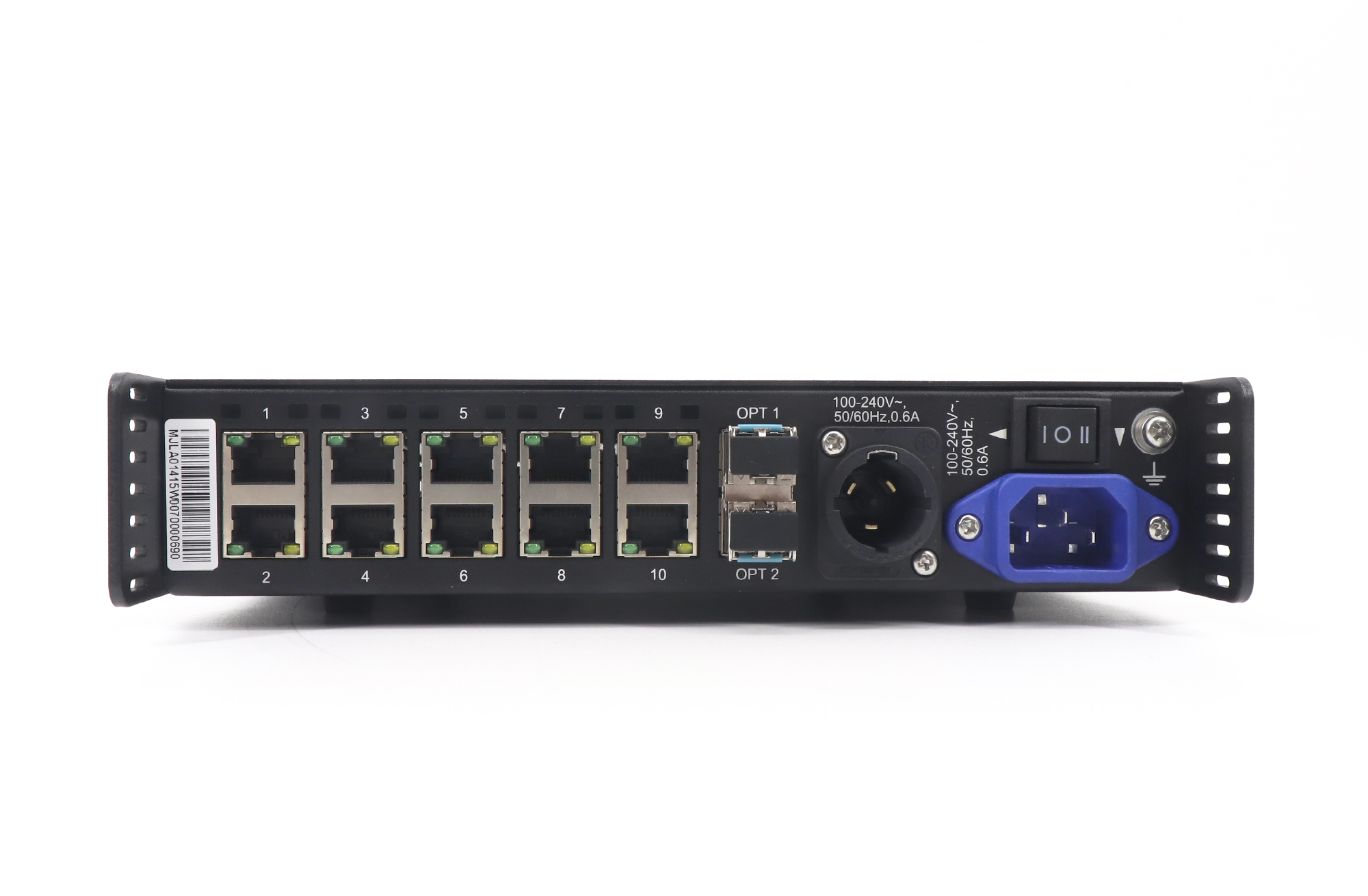
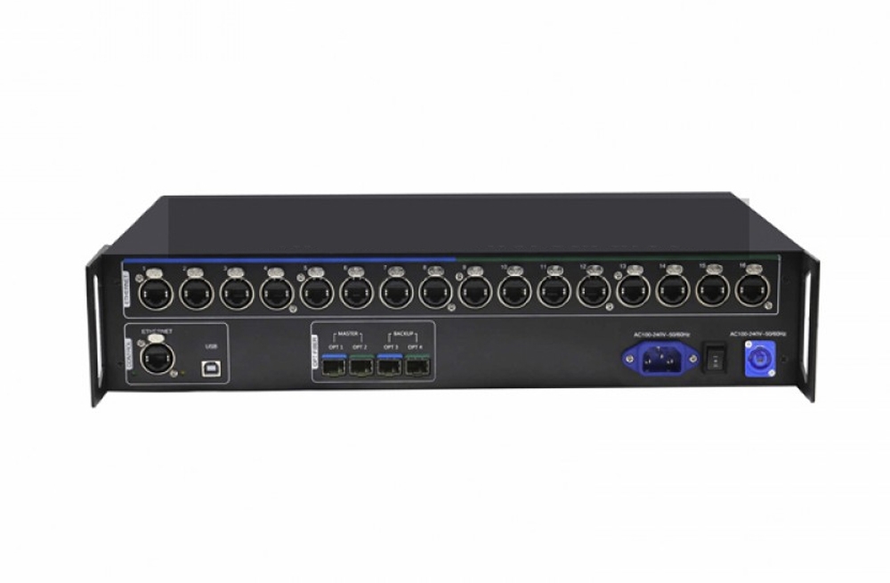
In fiber-to-Ethernet mode, NovaStar specifies CVT10 outputs 1 through 8 for compatible 10G sources using 8b/10b encoding, and outputs 1 through 10 for compatible 10.3125G sources using 64b/66b. When the CVT10 takes Ethernet in and sends fiber out, the published specification provides all ten Ethernet inputs. Select from the manufacturer’s documentation for the exact upstream output and transmission direction. A reseller’s description of your front-end processor as “10G” leaves the encoding unresolved.
If the design needs nine strings and the bill of materials assumes outputs 9 and 10, make confirmation of those outputs a condition of ordering the LED screen fiber converter. Send the processor model and the intended optical port, along with the controller’s software or firmware version and the cabinet map. Ask for a written answer that identifies the supported connection. For field troubleshooting, see why CVT10 ports 9 and 10 can be unavailable.
Make the feed count easy to audit. On the controller drawing, put the sender output, rack location and first cabinet of each chain on the same row. If a supplier proposes using eight feeds for a wall currently mapped to nine, ask the LED designer to check the proposed chain loads and reroute the cabinet cabling on paper. The revised drawing should show which cabinets moved, where the new chain starts and how a fault would affect the display. That gives purchasing a way to compare quotes for the same approved design.
02. Budget CVT4K optical groups separately
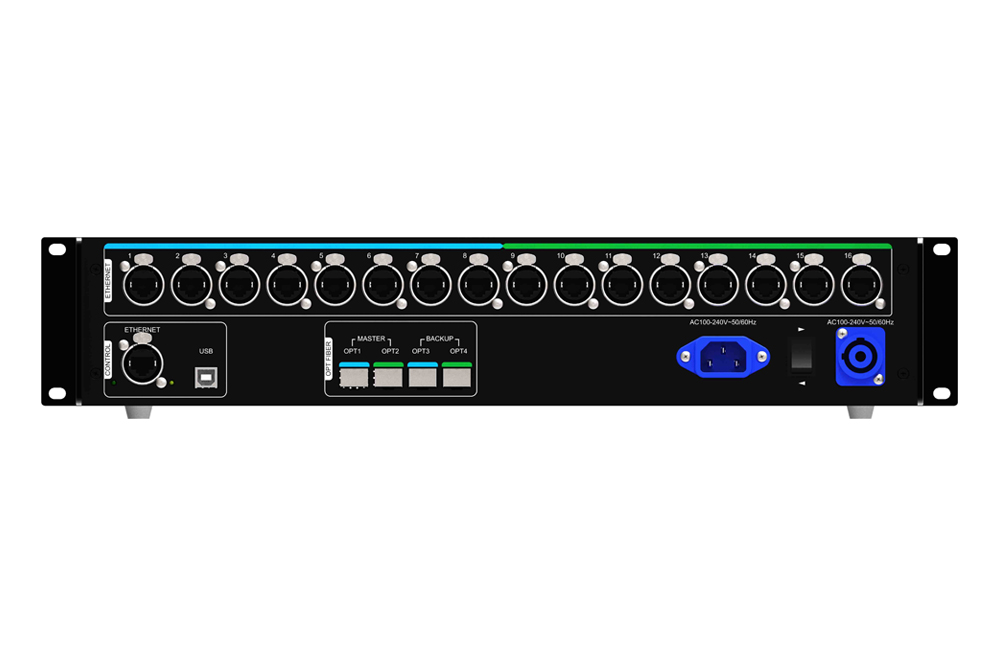
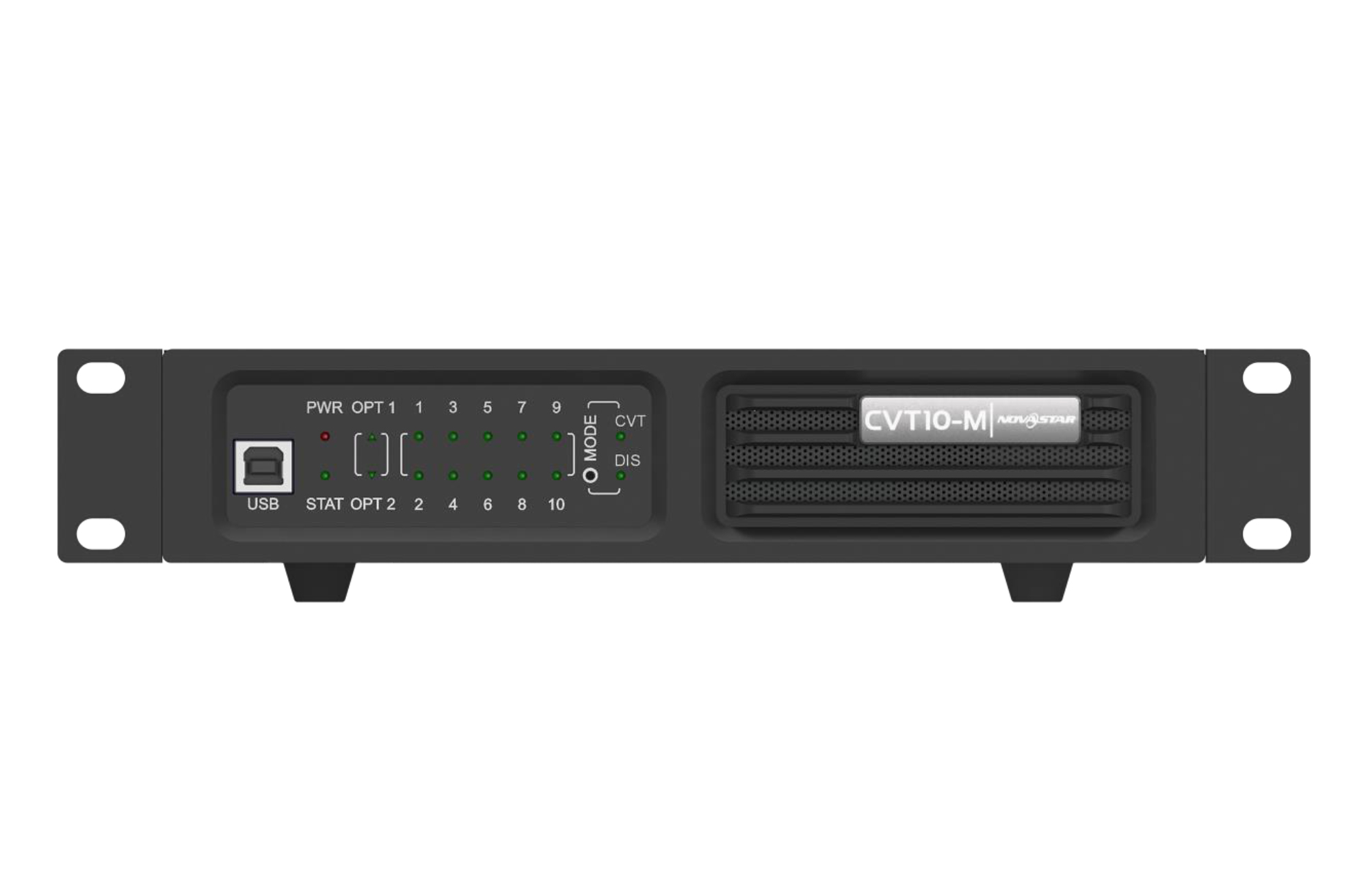
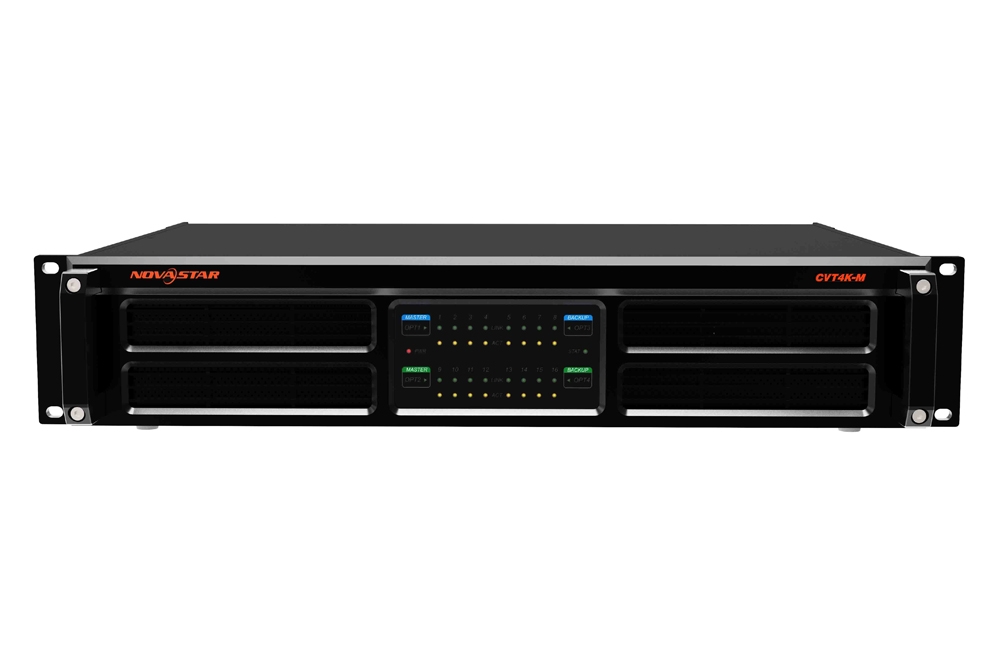
The CVT4K uses OPT1 for Gigabit Ethernet ports 1–8 and OPT2 for ports 9–16. OPT3 backs up OPT1 and OPT4 backs up OPT2. For a wall using twelve feeds, the second bank carries at least four feeds. Your sending-side equipment needs to originate the correct second group and your fiber schedule needs to carry it. An LED screen fiber converter can only deliver the feeds the sending system provides.
| Screen design | Model to evaluate | What to verify before ordering |
|---|---|---|
| Up to eight feeds on one compatible optical link | CVT10-S or CVT10-M | The exact upstream optical port, fiber suffix and numbered outputs assigned to the wall. |
| Nine or ten feeds on one compatible optical link | CVT10-S or CVT10-M with confirmed 64b/66b source | The source mode is 10.3125G 64b/66b and the system can drive every required output, including 9 or 10. |
| Eleven to sixteen feeds in one screen-side chassis | CVT4K-S or CVT4K-M | The sender supplies both eight-port groups and each group has a confirmed optical path. |
| Two eight-port groups with optical backup specified | CVT4K-S or CVT4K-M with documented backup topology | The sender, optics and routes support both primary and backup paths. Check the paired ports and test each group independently. |
These recommendations assume a compatible NovaStar signal path. They describe the distribution hardware and leave the receiver-card capacity and image-processing requirements to the LED design. NovaStar’s CVT10 product specifications define the encoding limits above. The CVT10 manual and panel reference provides more detail for that unit. The CVT4K-S and CVT4K-M specifications document the banks and backup assignments.
2. Match the optics to the installed route
01. Choose the S or M version from evidence
Select the suffix of your LED screen fiber converter after confirming the fiber at both ends and through each patch panel. For CVT10-S and CVT4K-S, NovaStar lists duplex LC single-mode OS1/OS2 fiber, 9/125 µm, and 1310 nm factory optics rated up to 10 km (6.2 mi). The CVT10-M and CVT4K-M use duplex LC multimode OM3/OM4, 50/125 µm, and 850 nm factory optics rated up to 300 m (984 ft). These are equipment ratings with matching optics and suitable link conditions. Agree on the allowable loss and verify the actual route before committing to it.
Ask the site team for a cable jacket marking, panel identifiers, a strand assignment and, when available, the route test report. A patch cord photograph proves something about the pictured cord. It might tell you very little about the trunk behind the wall. The site’s CVT10 cable-label guide explains what to photograph when the installed fiber is unknown. Approve a fiber type only after the records identify the complete path, including any intermediary segment under another team’s control.
02. Review the full path and reserve strands
Record the installed length and list patch connections, splices and any adapters from rack to rack. Ask the fiber contractor for the measured end-to-end loss at the relevant wavelength and compare it with the approved optics’ budget. A route well inside the distance rating can still be outside its loss budget. Check that both endpoints can use the specified optical modules and that polarity carries transmit to receive throughout the path. Two matching LC plugs establish a mechanical fit. The optics and link specification establish whether the signal can travel.
Show both working and spare fibers on the drawing for the LED screen fiber converter. For instance, two duplex optical groups use four strands for primary service. Two independently cabled duplex backups require four more assigned strands. This example assumes each link uses standard twin-core optics. Two links in one trunk can provide protection against some equipment or patch faults yet share the same risk from a cut to that trunk. If the project brief specifies physically separate routes, record the pathways and rack entry points explicitly.
For a retrofit, ask facilities to confirm who can release the strands and whether they are already reserved for another system. Include the patch panel and strand identifiers in the scope of work. The team may need new patch cords at both ends even with an existing trunk. If spare strands are scarce, price the alternate route and its approval lead time before promising optical backup. This can change the project cost more than the difference between converter models.
3. Build the order around your signal path
01. Decide whether the control rack needs a second chassis
A supported native optical output on the NovaStar controller can feed a compatible wall-side LED screen fiber converter directly. If the specified source offers electrical LED data outputs only, the design needs a supported electrical-to-optical conversion stage at the control rack as well as optical-to-electrical conversion at the wall. Ask for the approved exact sender and receiver combination for the direction and optical mode in use. Include either the native controller optics or the sending-side converter as an explicit line on the order.
Name each endpoint on the purchase schedule. If a chassis at each end is required, list both model numbers and suffixes, then match the optics and patch cords to each endpoint. Check whether the quoted units already include optical modules and which spare modules are recommended. Agree on rack brackets, connector retention, cable strain relief, service access and local power cords with the installation team. The control rack and the wall rack may have different space, ventilation and cable clearance limits.
02. Work two example orders from cabinet maps
Illustrative order A, nine feeds over existing multimode fiber. A meeting venue has nine cabinet strings and a tested 140 m (459 ft) OM4 route between racks. The specified sender has an approved 10.3125G 64b/66b multimode optical output. A NovaStar CVT10-M at the wall is a candidate for the LED screen fiber converter. Quote compatible sending-side optics if they are absent, the screen-side unit, duplex LC patching at both ends and the copper feeds. Add an acceptance line requiring correct image mapping from all nine assigned outputs. A supplier substitution that supports only eight outputs changes this order.
Illustrative order B, twelve feeds with two optical groups. A concourse has twelve cabinet strings and a tested 800 m (2,625 ft) OS2 route. Compare the NovaStar CVT4K-S as the screen-side LED screen fiber converter. If the proposed sender supports its two optical groups, allocate eight strings to the first group and four to the second. Ask for a route and connector schedule for both groups. If the owner wants optical backup for each group, quote separately assigned backup fibers and verify the supported sending-side backup arrangement. Keep a list of what can continue running under each failure scenario the owner cares about.
If the owner changes from OS2 to an existing OM4 path, recalculate the full installed length and loss and verify the sender optics again. The NovaStar CVT4K-M is the multimode version, with a different reach and a different optical specification. If a proposal substitutes CVT10 Pro for CVT10, confirm its exact optical suffix, encoding support, locking copper connectors and rack requirements using the Pro documentation. Similar model names belong on separate quote lines.
4. Compare complete quotes and agree on acceptance
Compare proposals on the cost of a working link. A low line price for one LED screen fiber converter can omit the sending-side chassis, optics, short patch leads, rack hardware or tested strands. A complete installed cost may also include fiber certification, labeling, commissioning time, freight and applicable tax or duties. For an existing fiber route, ask who pays if the fibers can be identified but fail the required loss test.
| Quote line | What the vendor should identify | Acceptance evidence |
|---|---|---|
| Active equipment and optics | Exact sender and converter SKUs by rack, number of optical modules included and optional spares | Inventory and labels match the approved connection drawing. |
| Fiber and copper patching | Fiber class, connector type, patch lengths, strand pairs and cabinet feed numbers | Route records and installed labels can be traced to each numbered connection. |
| Rack installation | Mounting parts, depth and clearance allowances, cord type and cable management | Installer confirms the racks, outlets and service access before shipment. |
| Optional failover | Which failures are covered, required extra optics or strands, and any route separation | Witnessed test of each promised backup path and recorded behavior on return to primary service. |
| Commissioning and handover | Who tests the route, maps cabinet feeds, and supplies the port map and configuration files | A signed checklist identifies the exact working model, link and mapping at each end. |
Before shipment, ask the supplier to agree on the exact optics, numbered cabinet outputs and backup behavior in the approved design. Have the commissioning team assign a test pattern or logical cabinet group to every required feed. An LED screen fiber converter can show a link light even when the picture is missing or misrouted. Confirm the cabinet image, inspect the image across group boundaries and retain a copy of the as-built port and strand schedule.
If the link has backup paths, agree on a maintenance window and have a qualified technician test the specified failure modes with the project team. Verify one bank at a time. Log the screen behavior, the indication at each endpoint and the recovery when the primary path returns. The outcome provides a basis for accepting the installation and gives the next technician a record of what the LED screen fiber converter is expected to do.
Set out the limits of the backup design in the quote. For example, two optical paths that terminate at the same CVT4K can cover an optical path fault in a supported topology. A loss of that chassis could still take both paths down. If continued service after a converter or controller failure is part of the contract, have the designer specify and price the additional hardware and wiring. Keep that acceptance test separate from a test of one fiber link. Documenting the difference helps the client compare bids with different redundancy assumptions.
Put the agreed configuration in the purchase order or attach the approved drawing revision. Ask the vendor to flag any proposed substitution before shipping. That gives the installer time to review a different hardware revision, optical module or accessory kit. Agree on who keeps the spare optics and the installation record, especially when facilities and the AV service contractor own different parts of the system.
Frequently asked questions
Does the name CVT4K mean the converter sets the maximum display resolution?
The converter distributes LED data. Establish the allowable canvas and the per-port pixel load from the sending system and the receiving-card configuration. A CVT4K can expose more cabinet outputs than a CVT10, while the controller still sets the usable canvas and pixel budget for your settings.
Can I run the signal through the venue’s existing network switches?
Use a vendor-approved signal path. Gigabit Ethernet connectors and a familiar optical module shape alone do not establish that an LED screen fiber converter will interoperate with an existing switch. Ask the system designer to document the link or assign passive fiber strands dedicated to the LED signal.
What should I stock as a spare if we maintain several venues?
Record the exact chassis and optical suffix at each venue. Where systems differ, build the spare list by supported equipment combinations. If you propose one spare LED screen fiber converter for multiple sites, verify the optics, active port count and mapping at every site before standardizing on it.
Can I approve the multimode version if the jacket says OM2?
NovaStar specifies OM3/OM4 for the factory multimode optics in the CVT10-M and CVT4K-M. If a route contains OM2, ask the system designer for a supported alternative and a documented link budget. Treat mixed or unidentified segments as a survey item and resolve them before buying the optics.
How should I specify a phased expansion from eight to twelve cabinet feeds?
Ask for a quote based on the final port map and put phase-one and phase-two parts on separate lines. If the plan uses both CVT4K banks, allocate rack space and fiber for the second group during phase one and confirm the sender can originate that group. Record the extra optics and patching needed to activate it later.
Request a quote for the complete link
To quote the LED screen fiber converter and the parts around it, send the controller model and intended optical output, the cabinet feed count and port map, the jacket or fiber test report, the rack-to-rack distance, and any backup requirements. Include the destination country for the cord type and freight scope. Review the CVT10-S product listing if you are pricing the single-mode, ten-socket chassis. Request a configuration and quote from LEDControllerCard.com with those details so the order can name both endpoints, the correct optics and each required cable.